HITEC Eclipse 7 User Manual
Page 13
Aircraft(ACRO) Section
13
Simple Transmitter Setup - Aerobatic Airplane (ACRO)
The following pages will take you step-by-step through the setup process for a sport or aerobatic airplane in the
ACRO menu. Going through this complete section will help you learn how to use your system quickly and
easily. If you need to set up a helicopter or glider, please refer to the quick setup instructions in the helicopter
and glider sections.
The aircraft setup procedure presented below uses an
aerobatic model as an example and assumes that there
are two aileron servos, one in each wing. You can use a
similar procedure to set up your own model; your setting's
numbers and percentages will probably be different.
If your model only has one aileron servo, skip the instru-
ctions referring to flaperon.
1. Be sure that all of your servos are plugged into the
proper receiver channels:
CH1 - Right aileron
CH2 - Elevator
CH3 - Throttle
2. We recommend that you do this programming exercise
with the servos installed in the model and connected to
the respective control surfaces. This will enable you to
immediately see the effect of each programming step.
3. Turn on your transmitter while holding down the two
Edit keys (the two keys on the far left). This gets you into
the model select (M.SEL) menu. Press the Cursor Right
button to move to a new model memory. The selected
model memory you select is indicated by the little flashing
arrow pointing down.
Memory #2 is shown here.
AIRCRAFT SETUP INSTRUCTIONS (AEROBATIC PLANE)
4. Press the Up arrow until the word ACRO appears,
flashing on and off. If it does, you're ready to proceed
on to the next step. If not, press the Left or Right
Cursor keys until it appears. You must press both Data
keys to "Save" the setting, after which the radio will beep
twice. This is how you select the type of model you wish
to use, either ACRO, HELI, or GLID.
5.
WARNING: selecting a different model type will erase
the settings in the model memory. BE SURE you're in the
correct model memory before selecting a new model type,
or you might accidentally erase a model you're using. (The
other memories will not be affected.)
6. Press the Up arrow once. This gets you into the
model name mode (note the words "MODEL" and
"NAME" in the upper left of the display).
7. Now you can select four letters to identify your model.
With the first of the four letters flashing, press the Data
+Increase or -Decrease key to change the letter that is
displayed. Stop when the first letter is the one you want.
8. Press the Right Cursor key once to get to the second
letter. Repeat the previous step to choose the second
letter.
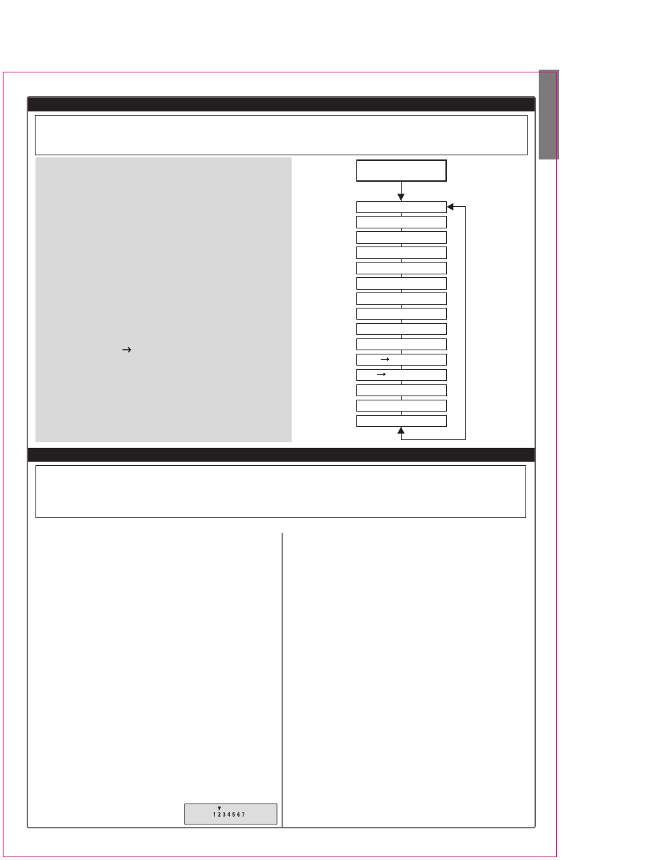
AIRCRAFT (ACRO) MENU FUNCTIONS
This section describes the menu functions for fixed-wing aircraft, provides a detailed setup example, and then
describes the functions individually. Functions relating specifically to gliders and helicopters may be found in the
following sections.
CH7 - (optional)
End Point Adjust [EPA]
Dual Rate Set [D/R]
Exponential [EXP]
Flight Cond. [FLT.C]
Sub-Trims [S.TRM]
Servo Reversing [REV]
Throttle Cut [T.CUT]
Prog. Mix 1-5 [PMX-]
Landing [LAND]
Flap Trim [FLPT]
Elev Flap Mix [E-F]
Ail Rud Mix [A-R]
Elevon Mix [ELVN]
V-Tail Mix [VTAL]
Flaperon Mix [FLPN]
Voltage/Timer Display
Normal Display Mode
Press both
Edit/Display key
CH4 - Rudder
CH5 - Gear
CH6 - Left aileron
ACRO Functions Map (see right)
Simple Aerobatic Airplane Transmitter Setup 13
EPA
End Point Adjust (servo travels)
18
D/R
Dual Rates
18
EXP
Exponential Settings
20
FLT.C
Flight Condition Select
20
S.TRM Subtrim
21
REV
Servo Reverse
22
T.CUT Throttle Cut (engine shut off)
22
PMX1-5 Programmable Mixer #1 - #5 (five total) 22
LAND Landing function settings
23
FLPT
Flap trim
23
E->F
Elevator Flap mixing
23
A->R
Rudder Coupling
24
ELVN
Elevon mixing (tailless models)
24
VTAL
V-tail mixing
25
FLPN
Flaperon (combined flaps & ailerons)
26
Aircraft Trimming Chart
27