HITEC Eclipse 7 User Manual
Page 15
If the rudder moves in the wrong direction, move over to
Channel 4 by pressing the Cursor Right key. Now the
'4' should be flashing in the display. Activate the opposite
direction for the rudder servo by pressing the Active/
Inhibit (Clear) key. Move the left-hand stick left-and right
again and verify the rudder moves the right direction.
If your model has retracts, set the correct response direc-
tion when commanded by the Gear switch, using the
same procedure. If you're using a second aileron servo,
you'll now set the left aileron servo direction (otherwise
skip this and the next step). This is channel 6, and the '6'
should be flashing for this command. When you move
the right-hand stick to the right, the aileron on the left wing
should move downwards. Check that the left aileron
moves the correct way! If it does not, activate the oppo-
site direction for the left aileron servo using the above
procedures. Move the right-hand stick again and verify
the left aileron moves in the proper directions.
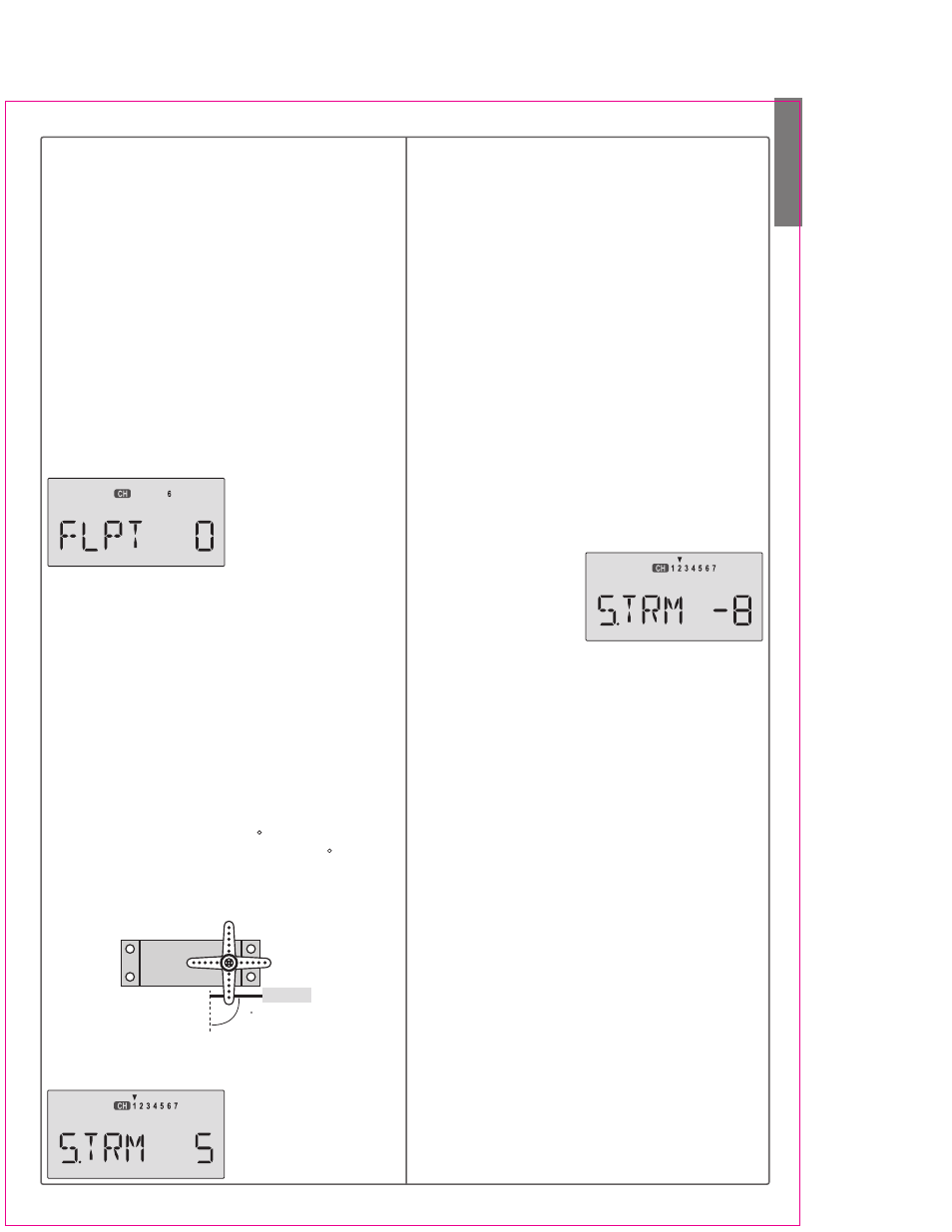
Press the Up or Down
arrow keys to the Flap Trim
function (FLPT), and input
a percentage of zero (0)
using the Data -Decrease
key. This temporarily disables the flap knob (VR1) so that
you can set aileron neutrals without regard to the flap
knob position. Later we'll turn it back on.
24. Before we set the servo neutrals, we need to be sure
that all the trims are centered. Press both Edit keys to get
to the main menu, where voltage and time are displayed.
Press the Up arrow until the word TRIM appears.
By moving each of the four trim levers around, you can
see their positions, and move them back to zero for the
next step.
25. Once you have centered all the trims, unscrew the
screws holding the servo arms onto the elevator, aileron,
and rudder (we'll set the throttle travel later). You will
want to place the servo arms on the output shaft so they
are near neutral - that is, about 90 to the servo case
sides or, if the servo is mounted sideways, 90 to the
pushrod (sideways mounting is not recommended).
This way you won't run out of subtrim authority. Remove
all the arms that are in the way or interfere with your
pushrods.
Adjust the clevises on each servo pushrod to get the
position of each control to be as close as you can to
neutral (lined up with the adjacent portion of wing or tail).
Setting Subtrims. Now
we'll adjust all the subtrims
to electronically set the
desired neutral locations.
To do so, go back to the
programming menu by pressing both Edit keys, then
press the Up or Down arrow key repeatedly until STRM
appears.
26. Set the right aileron subtrim first. If the little arrow is
not pointing at channel 1, press one of the Cursor
Left or Right buttons until it is (see figure). Then, adjust
the subtrim amount by adding or subtracting with the
Data +Increase or -Decrease keys. When you reach a
place where the right aileron matches up with the fixed
portion of the wing, you are done. If you can't get both
to match up, then set the subtrim back to zero and
mechanically adjust the clevis to get as close as you can,
then readjust the subtrim if necessary.
27. Note 1: you should NOT use subtrims instead of
mechanically adjusting the pushrods to be close. This
is because you can reduce the travel of the servo,especi-
ally if you have to set the subtrim near 100%. As we
stated before, get the pushrods close mechanically first,
then use the subtrim adjustment to get it just right.
28. Note 2: if you mess up the number you've entered
or find the percentage the wrong direction, you can get
back to zero quickly by pressing the Active/Inhibit
(Clear) button.
29. Repeat the subtrim
adjustment with the eleva-
tor servo (CH2). First set
the pushrod length mecha-
nically to get as close to neutral as possible, then set the
subtrim to get the elevator lined up to be parallel with the
stabilizer portion. For full-flying surfaces, use an incid-
ence meter or another method to get the incidence angle
recommended by the kit manufacturer or model designer.
30. For the throttle, we recommend not setting a subtrim
at this time. You will use the trim tab on the transmitter
for setting your idle RPM. To shut off the motor you will
use the Engine Cut function. In this way, you don't lose
your carefully-set idle position.
31. Most people set up their engines to idle with the
throttle trim near center, so that there is room for changes
due to humidity and other factors.
32. The Eclipse 7 provides a special throttle trim function
which allows the throttle trim lever to work at low throttle
levels, but disables it at high throttle.
33. Repeat the subtrim adjustment with the rudder (CH4),
gear (CH5), 2nd aileron channel (CH6), and the CH7
function if used. As before, first set them mechanically,
then adjust the electronic settings. Be sure you have
selected the appropriate channel number each time.
34. Servo EPA (End Point Adjustment). Now we'll go
through and set the servo travels for each channel.
This is both helpful and important, because you can set
the throw of each servo, in each direction, so that there is
no binding. Binding is important because it causes very
high current drain, and can lead to a battery dying pre-
maturely. Another use for the EPA function is to adjust
the model's total throws to match the recommended
Aircraft(ACRO) Section
15
Servo
Pushrod
90