HITEC Eclipse 7 User Manual
Page 21
Aircraft(ACRO) Section
21
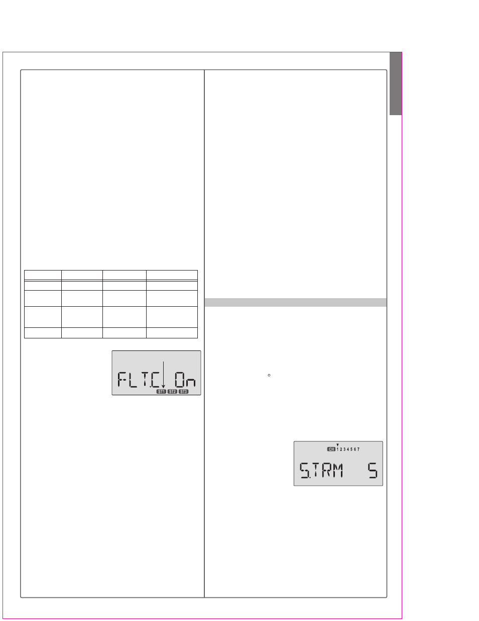
STRM- Subtrim Settings
Fit. Mode Switch Flt. Cond Switch
Active Flight Cond.
Comments
Any position
ST3
ST3 overrides all
Forward
Forward
ST2
ST2 active if ST3 off.
LAND also on.
Back
Back
Back
Back
ST1
ST1 active if ST3 off.
(E->F on)
Center
NOR
Default condition
Choosing Flight Conditions
1. Get to the FLT.C screen
with the Edit Up Down
keys. The display will indi-
cate "Inh" and, depending
on the positions of the two
controlling switches, one of the condition displays on the
bottom (ST1, ST2, or ST3) may be flashing.
2. Select the desired flight condition from the third colu-
mn of the table above, and move the two switches to
the positions shown on the same row of the table. The
active condition indicator on the bottom right of the dis-
play will flash.
3. Activate the selected flight condition by pressing the
Active/Inhibit (Clear) key. The letters "Inh" will change
to "On". Note that you cannot activate ST1 or ST2 if the
Flt. Cond switch is Forward, even if ST3 is currently
inhibited.
4. Repeat this procedure to activate each desired flight
condition. You can activate up to three conditions (be-
sides the normal one, which is always on). In this dis-
play, you can tell if you are in the NOR mode if the dis-
play indicates "Inh" and ST1, ST2, and ST3 are NOT
flashing.
5. Verify that the desired flight conditions operate when
the appropriate switch combination is selected by look-
ing at the flashing displays.
For example, you might have a scale model which is very
sluggish at lower speeds (such as takeoff and landing)
yet is very sensitive at higher speeds. Or, it may need lots
of rudder trim at lower speeds, but not at higher speeds.
Flight conditions allow you to choose between up to
three different individual sets of trims, dual rate set-
tings, and exponential values. You make the change
when either the Flt. Mode 3-position switch or Flt. Cond.
switch is flipped. The Eclipse 7 provides three flight
conditions in addition to the normal one (NOR), denoted
ST1, ST2, and ST3 (you will see these indicators in the
display). Flight conditions are a very unusual feature for
a system in the class of the Eclipse 7 and they are
normally found only on systems costing far more. As you
learn to use them, you will really appreciate them.
The priority of the conditions (when all three are activated)
is as follows: ST3 > (ST1, ST2) > NOR. In other words,
whenever ST3 is turned on, it has priority over the other
conditions. If ST3 is not on, both ST1 and ST2 override
NOR, which is only active if all the others are turned off.
This is better understood if you look at the table below:
6. Now that you have activated one or more flight condi-
tions, you can have new sets of dual rates, exponential
values, and trims. Trims are defined by the trim levers
on the transmitter, but you can define the values of D/R
and Expo using the programming menu. Use the Edit
Up Down key to move to the D/R menu.
7. With D/R indicated in the display, be sure the flight
condition switches are in the desired position by check-
ing to see which is flashing. Then input the desired D/R
value for the active condition. Note that you can only
define one rate for each flight condition - the position of
the Dual Rate switches does not matter.
8. Again use the Edit Up Down keys to get to the Expo
menu, and set up a desired value of expo for each flight
condition. Again, you can only select one exponential
value for each flight condition.
9. Return to the regular operating mode by pressing the
two Edit Up Down keys simultaneously. If you move to
the TRIM menu with the Edit Up Down key, the flight
condition indicators are shown in the lower right of the
screen, to tell you which is active. You can change the
trims in one flight condition, and they are stored separa-
tely and called up when you switch between them. That's
really cool!
The Subtrim window is used to make small adjustments
or corrections in the neutral position of each servo, inde-
pendent of the trim levers. The recommended procedure
is to zero out both the trims (see settings menu) and the
subtrims (this menu). Then, one mounts the servo arms
and sets up linkages so that the neutral position of each
control surface is as close to where it should be as possi-
ble, with the arm 90 to the pushrod. Finally, small
amounts of subtrim are used to make fine corrections.
We recommend that you try to keep all of the subtrim
values of as small as possible. Otherwise, when the
subtrims are large values, the servo's full range of travel
may be restricted.
Setting Subtrims
1. Use the Edit Up Down
keys to call up the STRM
window.
2. Press the Cursor Right
or Left key until the small
arrow is above the channel you wish to adjust (the figure
shows subtrim adjustment for CH1).
3. Adjust the neutral position using the Data +Increase
or -Decrease keys. You may adjust between -100% and
+100%. If you want to reset the value back to zero,
press the Active/Inhibit (Clear) key.
4. Repeat steps 2 and 3 for each channel to be adjusted
in turn.
5. Return to the regular operating mode by pressing the
two Edit Up Down keys simultaneously.
Flashing