View a view b, View a – FeiYu Tech FY-41AP User Manual
Page 9
GuiLin FeiYu Electronic Technology Co., Ltd. http://www.feiyudz.cn E-mail: [email protected]
Page 8
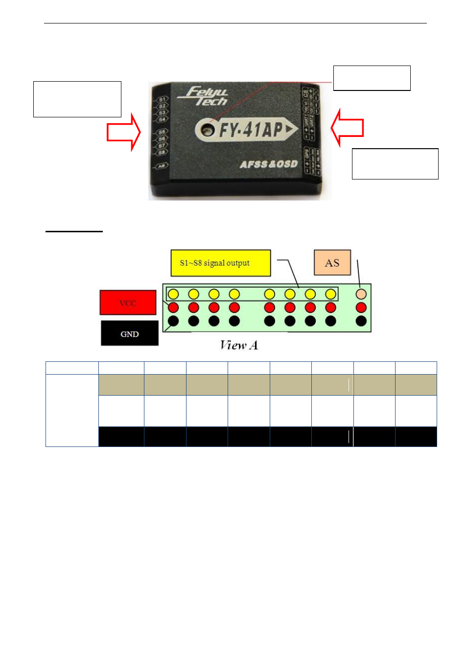
FY-41AP CONNECTION INTERFACE
VIEW A
Interface diagram:
No.
S8
S7
S6
S5
S4
S3
S2
S1
Servo
Output
Interface
P2
P1
N
AIL2
RUD
THR
ELE
AIL
Power
+5V
Power
+5V
Power
+5V
Power
+5V
Power
+5V
Power
+5V
Power
+5V
Power
+5V
GND
GND
GND
GND
GND
GND
GND
GND
A) The Yellow pins S1 ~ S8 are signal output to aircraft servos.
S1
: connect to Aileron servo 1 (same signal as S5).
S2
: connect to Elevator servo.
S3
: connect to ESC or engine throttle servo.
S4
: connect to Rudder servo.
S5
: connect to Aileron servo 2 (same signal as S1)
S6
: not used for Airplanes
LED Indicator
View A
View B
See also other documents in the category FeiYu Tech Accessories communication:
- FY Autopilot & AFSS (7 pages)
- FY-G4 3-Axis Handheld Gimbal For Smartphone (2 pages)
- G4 3-Axis Handheld Gimbal (2 pages)
- G3 Gimbal (2 pages)
- FY-G3Ultra 3-Axis Handheld Gimbal (2 pages)
- FY-G3 Ultra 3-Axis Brushless Gimbal For Aircraft (2 pages)
- FY-Panda2 Autopilot (41 pages)
- FY-Panda2 Autopilot (51 pages)
- FY-Panda2 Autopilot (53 pages)
- FY-Panda2 Autopilot (74 pages)
- Panda Autopilot (53 pages)
- FY-41AP (32 pages)
- FY-41AP (18 pages)
- FY-41AP (30 pages)
- FY-41AP (35 pages)
- FY-41AP (28 pages)
- FY-41AP (31 pages)
- FY-41AP Lite (35 pages)
- FY-605 Data Radio (6 pages)
- FY-DOS (18 pages)
- FY-DOS (11 pages)
- FY-DOS (16 pages)
- FY-DOS (21 pages)
- FY-40A (8 pages)
- FY-901 (3 pages)
- FY-30A (13 pages)
- FY-30A (4 pages)
- FY-31AP (7 pages)
- FY-31AP (8 pages)
- FY-AHRS-2000B (14 pages)
- FY-AHRS-2000B (12 pages)
- Hornet-OSD (2 pages)
- FY-606 Data Radio (2 pages)
- FY-91Q (4 pages)
- FY-91Q (27 pages)
- FY-21AP (5 pages)
- FY-3ZT (57 pages)
- FY-ARHS-1200A (12 pages)
- FY-AHRS-1200B (8 pages)
- FY-Y6 (7 pages)
- FY-X4 (7 pages)
- FY-AP117 (1 page)
- FY-90Q (2 pages)
- FY-602 Data Radio (7 pages)