American Energy Systems O2 Catalytic User Manual
Page 65
65
MODEL O2 CATALYST INSPECTION & REPLACEMENT
CAUTION: Be certain that there is no fire in your Country Flame stove and that the unit has had sufficient time to cool.
CLEANING INSPECTION
To inspect the catalyst, look up inside the stove and locate the catalytic combustor stainless steel plate. Remove the four
bolts that allow the stainless steel plate to be removed. Inspect for a dirty or plugged combustor. If dirty, refer to the
cleaning information provided earlier in this section. Proceed to remove the combustor for cleaning. Once the catalyst is
cleaned, replace the cleaned catalytic system back into the stove.
REPLACEMENT INSPECTION
Visually inspect the catalytic combustor at least 3 times during the heating season to determine if physical deterioration
has occurred. Only replace the combustor if it has become damaged. Cleaning can improve catalytic combustor
performance so before throwing it away, always attempt to clean it before disposing of a non-functioning combustor.
Refer to the cleaning process defined earlier in this section. Replace the catalytic combustor with a complete kit by
contacting Country Flame or one of its local authorized dealers.
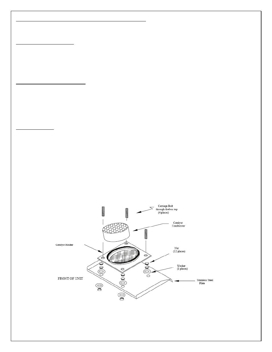
REPLACEMENT
Make sure your kit is complete and all parts are available for installation. Refer to FIGURE 20 to aid in the disassembly
and reassembly process. To remove the catalyst system, remove the eight nuts and eight washers along with the stainless
steel plate. The catalyst system will drop down so ensure that no mechanical damage occurs during the removal process.
Be prepared to handle the weight and ensure no damage occurs to the catalyst from mechanical shock.
To install a new catalytic system, assemble the catalyst and gaskets, if required, in the catalytic holder. Align this system
with the carriage bolts (4). Place four washers and then four nuts on the carriage bolts. Tighten with a wrench. Now
install the stainless steel shield and install four washers and then finger tighten the four nuts. There should be
approximately 5/8” thread exposed on each carriage bolt. Ensure the stainless steel plate is placed with the bent part up
and to the front of the stove. The catalyst holder has a stop on the bottom of the part. This stop ensures the stainless steel
shield cannot be drawn up too close to the holder and interfere with proper airflow.
FIGURE 20: CATALYTIC SYSTEM FOR MODEL O2 STOVE