Delta Electronics Network Device DOP-B User Manual
Page 6
English-5
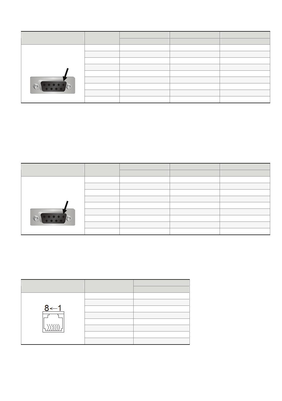
COM2 Port (Supports Flow Control)
MODE1
MODE2
MODE3
COM Port
PIN
RS-232
RS-422
RS-485
1 TXD+ D+
2
RXD
3 TXD
4
RXD+
5 GND GND GND
6
TXD-
D-
7 RTS
8
CTS
9 RXD-
Note1: Blank = No Connection.
Note2: When COM2 port is used for RS-232 flow control, i.e. RTS and CTS signals are used for flow control,
COM3 port will become incapable of being used.
Note3: When COM2 port is used for RS-422 flow control, please refer to the following COM3 Port signals table
for pin assignments. The signals, RTS+, CTS+, RTS- and CTS- shown in brackets are the signals used
for flow control.
COM3 Port
MODE1
MODE2
MODE3
COM Port
PIN
RS-232
RS-422
RS-485
1
TXD+(RTS+)
D+
2
RXD
3 TXD
4
RXD+(CTS+)
5 GND GND GND
6
TXD-(RTS-)
D-
7
8
9 RXD-(CTS-)
Note1: Blank = No Connection.
Note2: When COM2 port is used for RS-422 flow control, please refer to the COM3 Port signals table above
for
pin assignments
. The signals, RTS+, CTS+, RTS- and CTS- shown in brackets are the signals used for
flow control.
Ethernet Interface (LAN)
Contact
Ethernet Interface (LAN)
PIN
Ethernet
1 TX+
2
TX-
3 RX+
4
5
6
RX-
7
8
Note: Blank = No Connection.
PIN1
PIN1