Connecting the projector – Ask Proxima DP5950 User Manual
Page 10
Attention! The text in this document has been recognized automatically. To view the original document, you can use the "Original mode".
r
CONNECTING THE PROJECTOR
^^our projector is equipped wth various audio/video inputs and ou^uts including Computer HDB15-pin (VGA) termii
Monitor HDB15-pin (VGA) terminals and S-VHS video.
c
6>
inectin
0
th
¥=
co
№
CONNECTING TO
THE
COMPUTER INPUT HDB15-PIN
(VGA) TERMINALS (1 and 2)
Personal computers can be connected to the HDB15-pin (VGA) terminal on the projector.
• Connect the computer to these terminais using the VGA cable and VGA/MAC adapter (provided).
WARNING: For projectors, the VGA cable provided is designed to reduce RFI (Radio Frequency Interfere!
emissions. For regulatory compliance reasons, this cable must be used and must not be replaced by
m
other cable.
CONNECTING TO THE MONITOR OUTPUT HDB15-PiN (VGA) TERMINAL
This terminal contains the information that is viewed on the screen.
An external monitor can be connected to the HDBt 5-pin (VGA) terminal on the projector.
• Connect the monitor to this terminal using a monitor cable (not prodded).
HDS15-PIN
TERMINAL
5 4 3 2 1
O O O O O
10 9 8 7 6
o o o o o
o o o o o
.15 14131211
Pin No./Slgnal
1 Red input
2 Green input
3 Blue input
4 Sense 2
5 Ground (Horiz. sync.)
6 Ground (Red)
7 Ground (Green)
8 Ground (Blue)
Pin No./Signa!
9 Non Connect
10 Ground (Vert s;
11 Sense 0
12 Sense 1
13 Horiz. sync.
14 Vert sync,
15 Reserved
CONNECTING TO THE
COMPUTER AUDIO
INPUT
JACKS
(1
and
2)
• Connect audio outputs from your computer to these jacks using die audio cable (not provided).
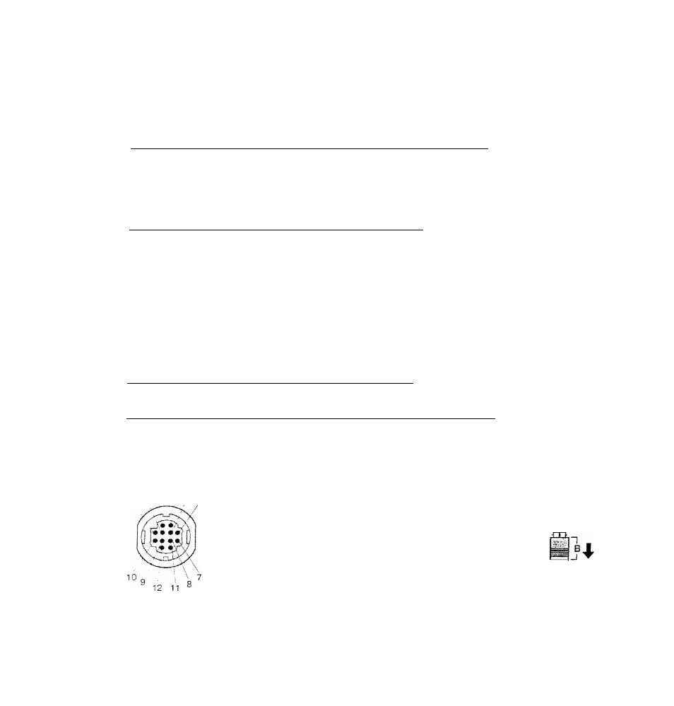
CONNECTING TO
THE
MULTI-POLE 12-PIN (CONTROL
PORT) CONNECTORS
(1
and
2)
• II you wish to control the computer with projector's remote control unit, you must connect control port (PS/2, Serial
ADB port! on your computer to projector's control port with a cable (three types of cables provided).
CONTROL PORT
.
2
1
6
8
10
11
12
pse
Port
CLK
DATA
GND
Serial
Port
TxD
•S- RxD
READY
GND
ADB
Port
ADB
GND
CONTROL PORT CABLE
REMOVAL HINT
Disconnect control port cable
with following steps.
1. Hold the portion (A) of the
connector with one hand.
2. Pull the portion (B) arrow
direcion and remove
F
connector,
i_
If
j
W'L NOTE: The RxD port (5 pin on the Serial Port) is provided on control port 2 connector only. If you control the projed
by computer, you must connect control port 2 connector.