Adjustments – Ariens 929000 User Manual
Page 82
Attention! The text in this document has been recognized automatically. To view the original document, you can use the "Original mode".
2. Turn the chute crank (6) Figure 13, so that
snow will be thrown in the desired direction.
3.
Lower the sno-thro and start the auger
rotating
by
pulling
the
implement
power
control
switch (1) Figure 12, "out" with the engine running at
'/3
fast throttle (7) Figure 12. Increase engine speed to
full throttle after the sno-thro auger is rotating.
On the S-8 and S-12 tractor the sno-thro is raised
by pulling the rhanual lift lever (3) Figure 13, until the
latch snaps into a notch of the control quadrant. To
lower sno-thro, pull lever slightly rearward, depress
button and move the lever forward.
On the S-14 and S-16 tractors with the hydraul
ically operated lift (4) Figure 12, raise the attachment
by moving the control lever to the UP position. The
sno-thro may be held in any position desired by
allowing the lever to stay in the "hold" position. While
operating the sno-thro, the lever should be moved to
the "float" position, to permit the attachment to
follow the contour of the ground.
4.
For maximum snow removal and discharge
operate the engine at full throttle and regulate the
travel speed with the hydrostatic control lever and/or
shift lever (5) Figure 12 and 13.
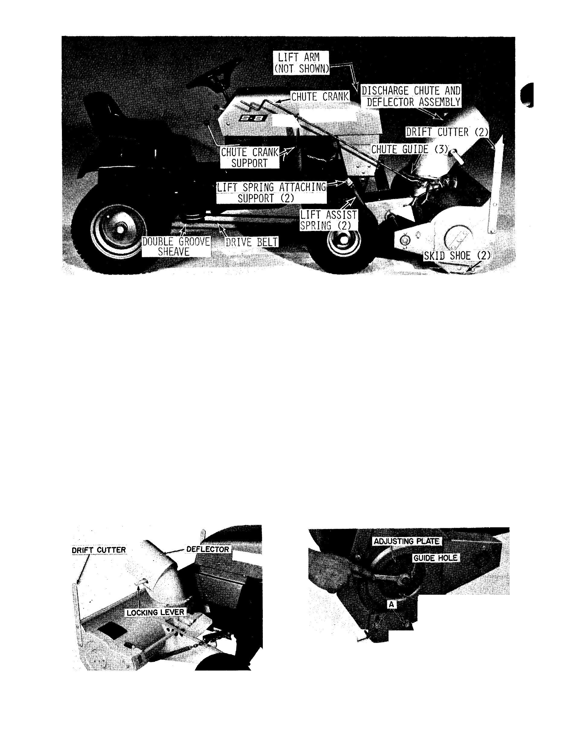
ADJUSTMENTS
1
. The deflector. Figure 14, has a slotted hole on
each side for adjustment. To change the angle of the
deflector, loosen the two locking levers. Tighten the
locking levers when the deflector is adjusted at the
desired angle.
2.
The runners. Figure 15, are mounted on
slotted
holes
to
provide
the
desired
clearance
between the base of the auger housing and the
surface of the area to be cleared. When operating on
a smooth surface such as cement or asphalt, the
runners can be set at the lower end of the slots as
shown. When operating on a rough surface such
i
as
PLATE MOUNTING HOLE
SKID SHOE
SCREWS REMOVED ■
FROM ADJUSTING PLATE ^
FIGURE 14
FIGURE 15
PAGE 82