Hydrostatic control lever brake adjustment, Front wheel toe-in adjustment – Ariens 929000 User Manual
Page 65
Attention! The text in this document has been recognized automatically. To view the original document, you can use the "Original mode".
í
HYDROSTATIC TRANSMISSION DRIVE BELT
(HYDROSTATIC MODEL ONLY)
The
hydrostatic
drive
belt
does
not
require
tightening. Belt tension is achieved by a spring-loaded
idler. Replace the belt if it has stretched or worn to the
point where it begins to slip.
HYDROSTATIC NEUTRALIZER PEDAL ADJUSTMENT
(HYDROSTATIC MODEL ONLY)
The linkage should be adjusted to automatically
return the hydrostatic control lever to the "park-start"
(neutral) position when the neutralizer pedal is de
pressed.
To adjust the neutralizer pedal, place control
lever in the "park-start" position, loosen bolt A,
Figure 33, depress the foot pedal and apply the brake
lock, then retighten bolt A.
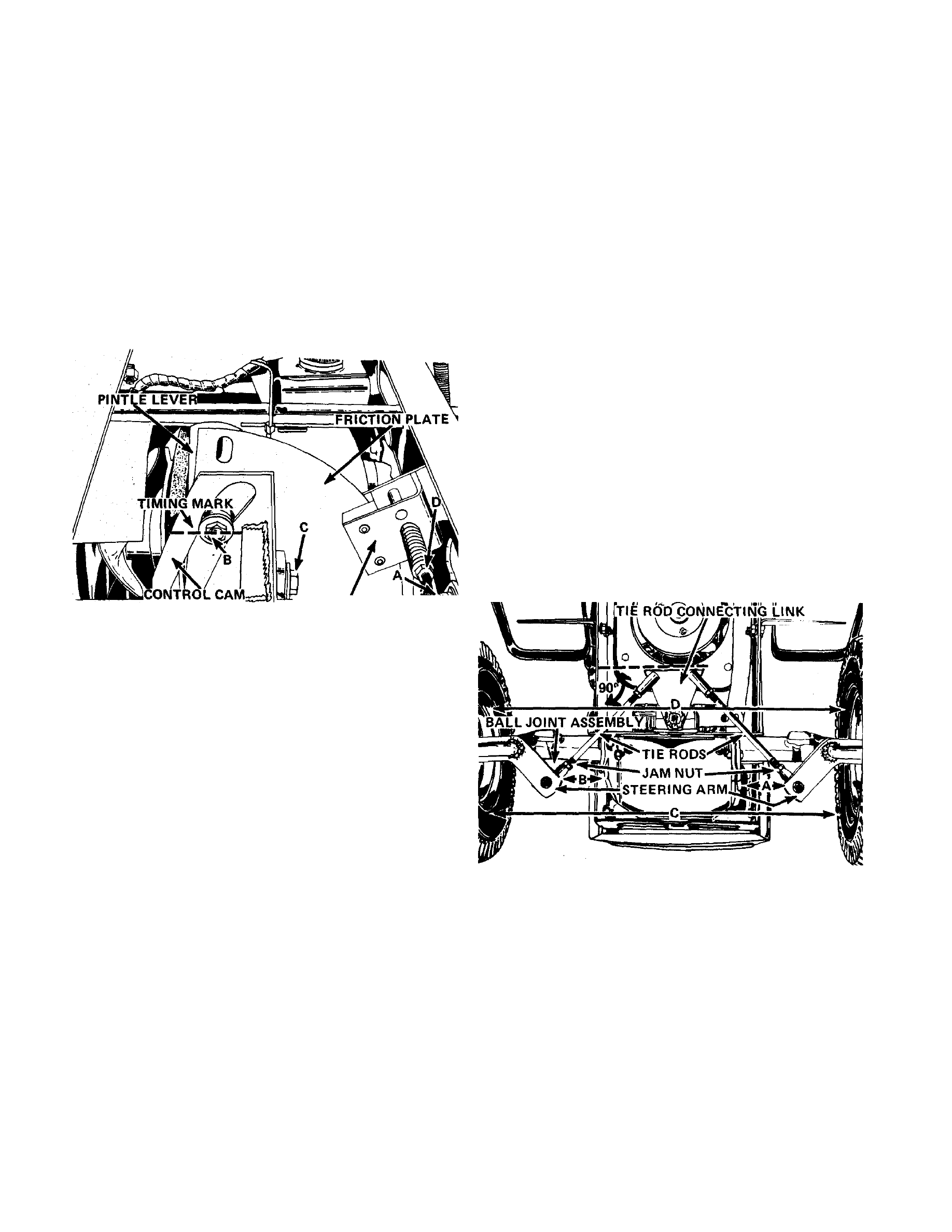
FRICTION BRAKE'-
Figure 33
Release brake lock, move the control lever to a
forward position then depress the foot pedal. The
control lever should return to "park-start" (neutral).
Repeat process by placing control lever in reverse.
When the adjustment is properly made, the control
lever will automatically return to neutral from either
forward or reverse when the neutralizer pedal is
depressed.
IMPORTANT:
NEVER
DEPRESS
BRAKE
PEDAL
AND
MOVE
THE.
HYDROSTATIC
CONTROL
SIMUL
TANEOUSLY.
THE
LINKAGE
IS
INTERCONNECTED
AND
DAMAGE
OR
MIS-ADJUSTED
LINKAGE
COULD
RESULT.
on the cam. If the timing mark does not align with the
bolt head, loosen bolt C and move the cam up or down
as required to align the bolt head with the timing
mark.
Tighten
nut
C
securely
after
making
the
adjustment.
3. Jack up rear of the tractor until rear tires are
clear of the ground.
4.
Start engine and increase speed to full
throttle.
5.
Loosen bolt B slightly. Insert a screwdriver
through the slots in the friction plate and the pintle
lever. Figure 33. Pivot the pintle lever left or right
until the rear tires stop rotating and retighten bolt B.
A
WARNING:
KEEP
HANDS
AND
ANY
LOOSE
CLOTHING
AWAY
FROM
THE
HYDROSTATIC
COOLING
FAN
AND
DRIVE
BELT
WHEN
MAKING
ADJUSTMENT.
THESE
PARTS
MUST
ROTATE
WHEN
MAKING
THE
NEUTRAL
ADJUSTMENT.
HYDROSTATIC CONTROL LEVER BRAKE ADJUSTMENT
The hydrostatic control lever friction brake must
be adjusted so the control lever moves through the
"forward" and "reverse" modes with a minimum of
force. However, due to the neutral tendency of a
hydrostatic transmission to neutralize, the brake must
be tightened sufficiently so the tractor maintains any
selected speed setting.
To adjust the friction brake, tighten or loosen bolt
D, Figure 33, until the proper braking is reached.
Figure 34
I
HYDROSTATIC NEUTRAL ADJUSTMENT
(HYDROSTATIC MODEL ONLY)
The hydrostatic controls should be adjusted so the
rear tires stop rotating when the control lever is
returned to neutral either manually or with the
neutralizer pedal.
Use the following procedure to adjust neutral:
1.
Check
HYDROSTATIC
NEUTRALIZER
PEDAL
ADJUSTMENT.
If
required,
adjust
as
previously
explained.
2. Check position of the timing mark on control
cam. With the shift lever in the "park-start" position
and brake lock engaged, the center line of bolt head
B, Figure 33, should be aligned with the timing mark
FRONT WHEEL TOE-IN ADJUSTMENT
Proper toe-in of the front wheels is necessary to
assure proper steering and to reduce tire wear.
Correct toe-in is when the front of the wheels are 1/8"
to 1/16" closer together than the rear of the wheels
(measured at the horizontal center line of the rim
flanges).
If the steering develops a wandering character
istic or if excessive tire wear develops, the toe-in of
the front wheels should be checked. If the toe-in is not
correct, adjust as follows:
1. Turn steering wheel until the rear edge of the
tie rod connecting link is perpendicular (90 degrees)
to the tractor frame as shown in Figure 34.
2. Adjust length of tie rods until distances A and
PAGE 65