36" sno-thro — model 829003, Assembly instructions – Ariens 929000 User Manual
Page 79
Attention! The text in this document has been recognized automatically. To view the original document, you can use the "Original mode".
ASSEMBLY INSTRUCTIONS
36" SNO-THRO — MODEL 829003
The 36 ST Sno-Thro is designed for use on all
kriens 929000 series Lawn Tractors.
"Left" and "right" are always determined from a
Position facing the direction of forward travel during
operation.
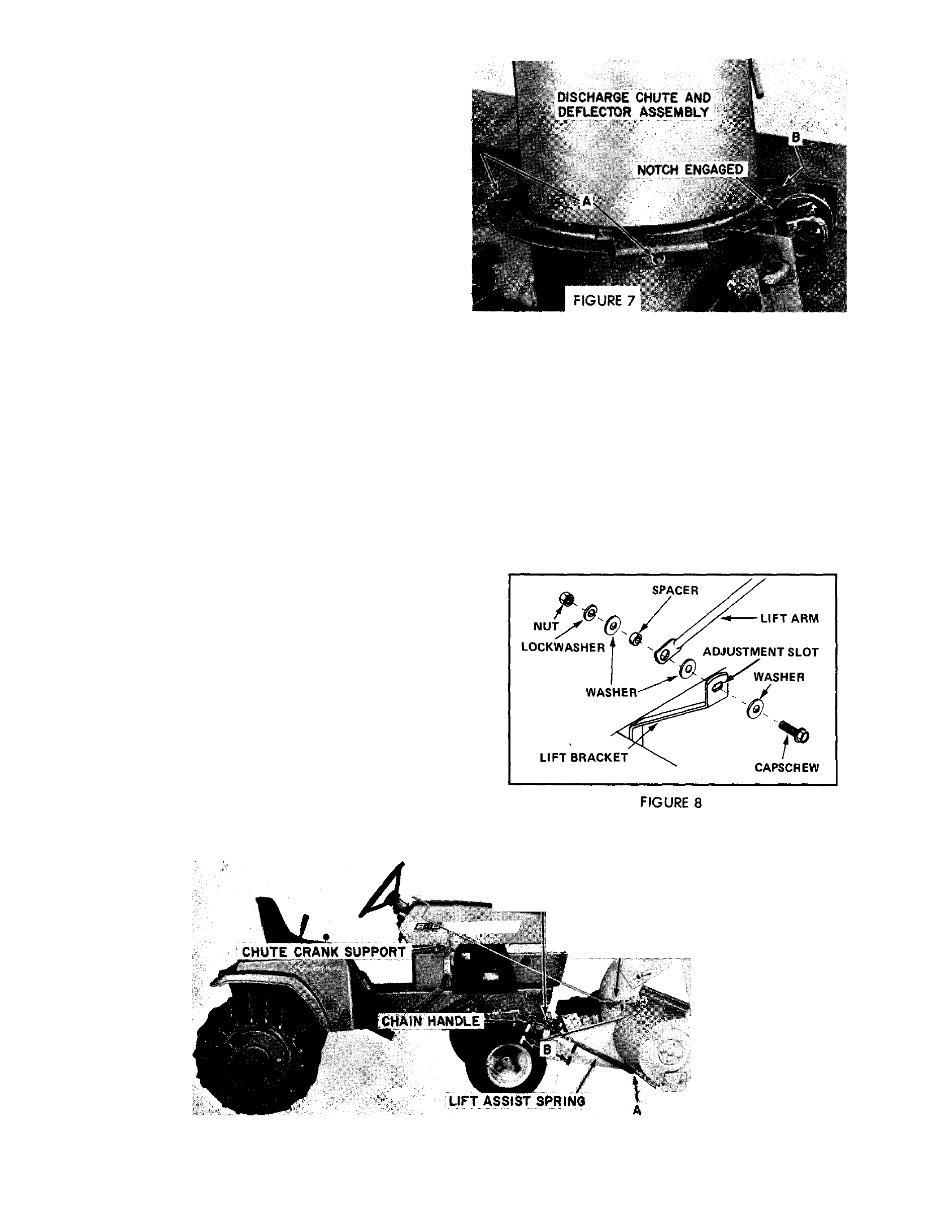
1.
Apply a light coating of grease to the
underside of chute base ring and position on the chute
and deflector assembly on the auger housing as
shown in Figure 7. The notches in the chute base must
engage the spiral control as shown.
Place the three chute guides over the base ring as
shown in Figure 7 and align the holes in the guides
with the holes provided in the auger housing. Secure
with 5/16" X carriage bolts, lockwashers and nuts.
Install nuts to the outside at Point A. Install nut to the
inside at Point B.
Turn the spiral control to assure that the chute
turns freely. If there is any binding, it may be neces
sary to pry the openings in the chute guides apart until
the chute turns freely.
2. Secure the drift cutters, Figure 6, to the auger
housing with 3/8" x %" capscrews, lockwashers and
nuts.
3.
Install the skid shoes as shown in Figure 6.
Install each shoe at the same height. Secure with 3/8"
X 1" carriage bolts, flat washers, lockwashers and
nuts. Place flat washers next to the slots.
4.
Insert chute crank through the hole in the
chute crank support, (Figure 6) and insert opposite
P
nd into universal joint on the snow head, Figure 10.
fecure with hairpin cotter,
5.
Remove front running board support mounting
hardware on the right side of the tractor. Position
chute crank support as shown in Figure 6. Secure with
3/8" X 1 Vi" capscrews, lockwashers and nuts.
6.
Remove the single groove mower drive sheave
from under the tractor and replace with the double
groove drive sheave as shown in Figure 9. Secure with
the square key and snap ring installed on the original
sheave.
A
CAUTION:
The
upper
sheave
must
be
used
to
drive the mower. The lower sheave must be used
to drive the sno-thro.
7. Attach lift arm to the lift bracket. Figure 8,
using a spacer, 3/8" x 1
Vi"
capscrew, three flat
washers, lockwasher and nut. Insert spacer through
hole in lift arm. Use one flat washer at each end of the
spacer. Use the third flat washer next to the slot on
the lift bracket. Secure with lockwasher and nut.
8. Loosen belt guides A, Figure 11, and install the
drive belt as shown. After installing the belt move belt
guides to a position 1/8" from sheave edge and bell
when belt is tight and secure the locking nuts.
CHUTE CRANK
/
ROCK SHAFT ARM
HAIR PIN COTTER
AND FLAT WASHER
\
FIGURE 6
PAGE 79