Transmission cooling system, Bleeding the transmission – Ariens 929000 User Manual
Page 60
Attention! The text in this document has been recognized automatically. To view the original document, you can use the "Original mode".
It is essential that the rotating screen, engine
cooling fins and the exhaust system be kept free of
dirt and debris which could cause the engine to
overheat.
To avoid overheating and possible engine dam
age, periodically remove the shrouding from
around
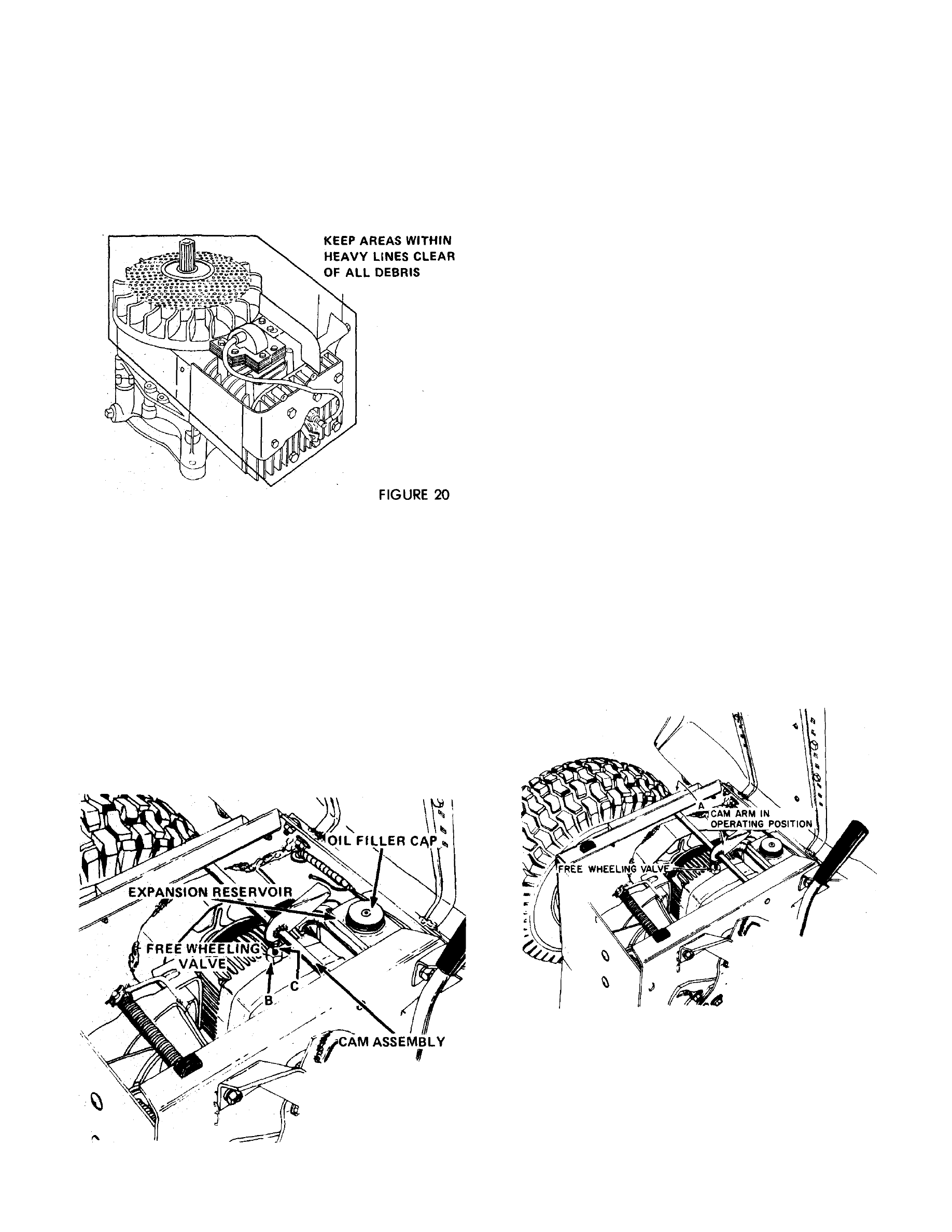
the cooling fins. Figure 20, and clean the area shown
within the heavy black line of all grass, dirt or chaff
accumulation.
TRANSMISSION COOLING SYSTEM
Dirt and grime occumulations on transmission
cooling fins can cause overheating. Check and clean
the cooling fins every 50 hours of operation or
quarterly. In extremely dusty or dirty conditions,
clean the cooling fins more frequently.
C A U T IO N :
R E S E R V O IR .
K E E P
WATER
A W A Y A N D O F F
Check the hydrostatic cooling fan blades periodi
cally to assure that the blades are not bent or broken
and that the fan is in good condition.
FiGURE 21
BLEEDING THE TRANSMISSION
If for any reason the oil level is ever permitted to
fall below the expansion reservoir, air may enter the
system causing the transmission to malfunction. If this
should occur, use the following procedure to "bleed"
(remove air from the transmission);
1. Thoroughly clean all dust, dirt and grime from
the free-wheeling valve, the oil filler cap and sur
rounding areas. Figure 21.
2. Remove nut A, Figure 22 from the left end of
the com assembly shaft and slide the cam assembly to
the right until the cam arm is free of the valve
actuating rod.
3. Loosen nut B first and then valve actuating rod
C, Figure 21, and remove the rod. Be extremely
careful not to allow dirt to enter the transmission.
4. Remove the expansion reservoir filler cap and
add 'Type A" transmission fluid until the reservoir is
Vi full.
5. Jack up rear of the tractor, start the engine
and operate at a slow idle speed.
6. With engine running, move speed control
lever to both forward and reverse positions until oil
appears at the free-wheeling valve hole.
7. Replace free-wheeling valve actuating rod C
and tighten nut B, Figure 2l, to 30 inch-pounds.
Tighten both parts carefully to prevent the small
rubber o-rings inside the cap from becoming dam
aged.
8. Replace cam assembly. Figure 22. Tighten nuts
A so the cam arm intersects the center of the valve
actuating rod and the shaft has 1/32" end play.
9. Recheck the oil level. If necessary add oil until
the reservoir is half full.
FIGURE 22
N O T E : T H E C A M A R M M U S T B E IN T H E F O R W A R D
P O S IT IO N
BEFORE THE
T R A C T O R C A N B E O P E R A T E D .
PAGE 60