Ariens 929000 User Manual
Page 63
Attention! The text in this document has been recognized automatically. To view the original document, you can use the "Original mode".
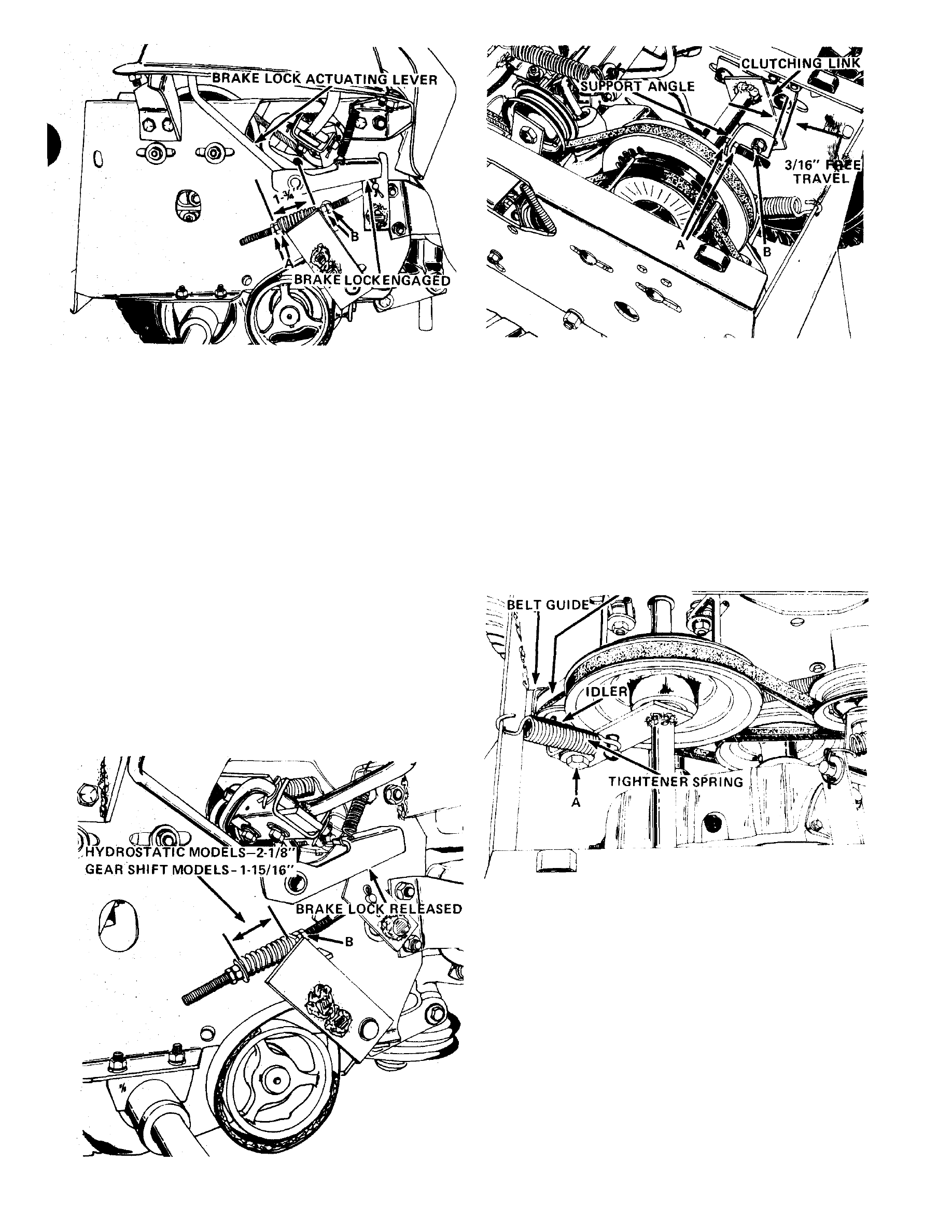
Figure 26
Figure 28
I
Sion spring measures 1% inch.
N Ò T E : N u ts B m u st n o t to u c h th e s u p p o r t w h e n
m a k in g th e a d ju s tm e n t. A llo w a t le a s t 1 / 1 6 " c le a r
a n c e b e tw e e n n u ts B a n d th e s u p p o rt w h e n a d ju s tin g
th e s p r in g le n g th .
3. Release brake lock and allow the brake pedal
to return to its normal position against the stop.
4. Tighten nuts B, Figure 27, until compression
spring measures as follows;
Hydrostatic models —2-1/8"
Gear shift models — 1-15/16"
N O T E :
T h e c lu tc h fr e e -tr a v e l m a y b e a ffe c te d
a fte r a d ju s tin g th e b ra k e . A d ju st if n e ce s s a ry a s
o u tlin e d u n d e r "C lu tch F re e T r a v e l A d ju s tm e n t ."
CLUTCH FREE TRAVEL ADJUSTMENT
(Gear Shift Models)
The clutch rod must be adjusted to insure that the
transmission drive belt is fully engaged when the
clutch brake pedal is released.
To adjust the free travel, move nuts A, Figure 28,
front or back so that when depressing the clutch brake
pedal the support angle moves forward 3/16" before
bolt B contacts the front of the slot in the clutching
link.
TRANSMISSION DRIVE BELT
Figure 27
Figure 29
TRANSMISSION DRIVE BELT
(Gear Shift Models)
The
transmission
drive
belt
idler
should
be
adjusted if the drive belt slips or if the spring coils
have bottomed out. See Figure 29. Adjust by loosen
ing bolt A and moving the idler back in the slotted
hole of the mounting bracket until the belt does not
slip and until there is clearance between the spring
coils. Before tightening bolt A, place the belt guide
1/8" from the belt in such a position that it does not
bind the belt in any position of the idler.
Check belt guide D, Figure 30. It should be
positioned 1/8" from the belt at the point where the
belt enters the drive sheave. Adjust by loosening the
PAGE 63