Intermediate shaft drive belt (gear shift models), Pto drive belt (implement power) – Ariens 929000 User Manual
Page 64
Attention! The text in this document has been recognized automatically. To view the original document, you can use the "Original mode".
mounting bolt A and positioning the guide as
required.
N O T E :
T h e c lu tc h fr e e -tr a v e l m a y b e a ffe c te d
a fte r a d ju s tin g th e d riv e b e lt id le r . A d ju s t if n e c e s sa r y
a s o u tlin e d u n d e r "C lu tch F re e T r a v e l A d ju s tm e n t ."
INTERMEDIATE SHAFT DRIVE BELT
(Gear Shift Models)
the intermediate shaft drive belt should be
tightened if it begins to slip or before the idler bracket
contacts the stop bolt as shown in Figure 30.
SHAFT PARALLEL TO REAR OF
TRACTOR FRAME WITHIN 1/16"'"
''1'-...................
To adjust the belt tension, loosen the four
intermediate shaft mounting bolts A and B, Figure 30,
and move the shaft rearward keeping it parallel to the
rear of the tractor frame until the front, edge of the
idler bracket is flush with the plate identified at C.
N O T E : T H E S H A F T M U S T B E P A R A L L E L T O T H E
T R A C T O R F R A M E W IT H IN 1 / 1 6 IN C H .
Adjust belt guides D and E 1/8" from the belt at
the points where the belt is tangent to the sheave and
tighten the shaft mounting bolts A and B.
N O T E : T h e clu tch fr e e -tr a v e l a d ju s tm e n t c a n b e
a ff e c te d
a fte r tig h t e n in g th is b e lt. R e -a d ju st a s
p r e v io u s ly o u tlin e d if n e c e ss a r y .
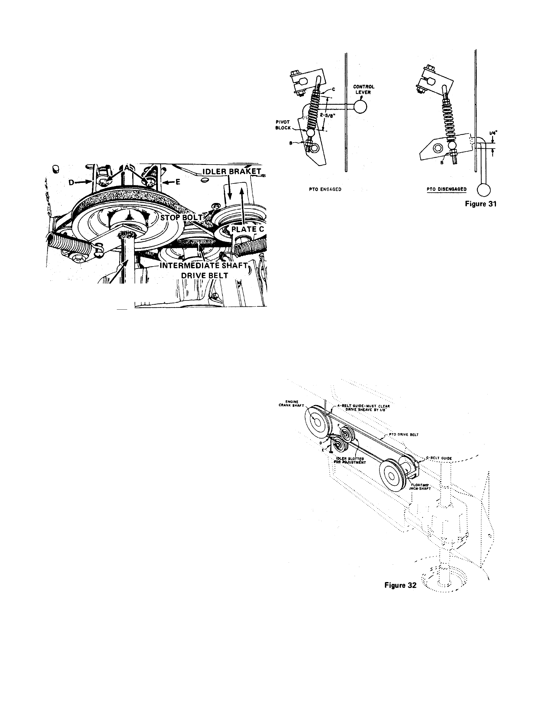
PTO DRIVE BELT (Implement Power)
The PTO drive belt should be adjusted before the
rear nuts B, Figure 31, contact the pivot block when
the implement power clutch is engaged or if the belt
begins to slip.
Use the following procedure to adjust the belt:
1.
Engage implement power clutch and tighten
nuts C, Figure 31, until the spring length is 2-5/8".
N O T E : W h e n m a k in g th is a d ju s tm e n t, th e r e m u st
b e c le a r a n c e b e tw e e n th e r e a r n u ts B a n d th e p iv o t
b lo c k . M o v e n u ts B r e a rw a r d if n e c e s sa r y to o b t a in
th is c le a r a n c e b e fo r e m e a s u rin g th e s p rin g le n g th .
PTO DRIVE OVERCENTER ASSEMBLY
Figure 30
2.
Position belt guides D and E, Figure 32, across
from one another when the clutch is disengaged in
such
a
manner that the belt is retained in the disen
gaged position. In addition, guide D must clear the
engine sheave by 1
/ 6 " a s
the clutch is moved from the
disengaged to the engaged position. Move guide D
rearward if necessary to obtain this clearance.
3.
With clutch disengaged, tighten nuts B, Figure
31, to obtain 1/4" clearance between the implement
power clutch lever and rear of slot in the tractor
frame.
If after adjustment, the rear nuts B, Figure 31,
contact the pivot block when the clutch is engaged,
loosen bolt F, Figure 32, and move the idler closer to
the belt to provide additional adjustment. Repeat the
complete adjustment sequence if it becomes i
necessary to move the idler.
i
i
1
PAGE 64