Vtr8300 series, User interface guide – Viconics VTR8300 Line Voltage User Interface Guide User Manual
Page 13
VTR8300 Series
13
User Interface Guide
Viconics Technologies Inc.
I Small Building Systems I 9245 Langelier Blvd. Saint-Leonard, Quebec, Canada, H1P 3K9 I +1 514 321 5660 I www.viconics.com
028-6045-01
April 2014
© 2
01
4 V
ic
on
ic
s T
ec
hn
ol
og
ie
s. A
ll r
ig
ht
s r
es
er
ve
d
.
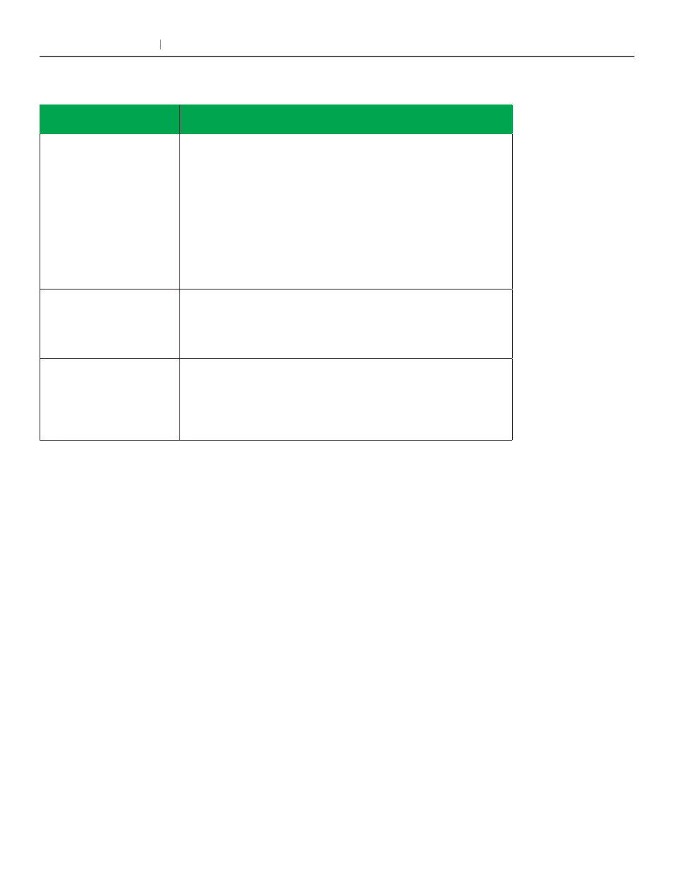
Configuration parameters
default value
Significance and adjustments
Fan cont. heat
Default is: On
Fan control in heating mode.
(On): the controller in all cases will always control the fan (terminals Low-
Med—Hi Fan Speed). Valid in any fan sequences and all the available fan
modes.
(Off Auto): the controller in all cases will disable the fan (any terminals Low-
Med—Hi Fan Speed). ONLY when the local fan mode is set to Auto. Valid
in all fan sequences with auto mode.
(Off All): the controller in all cases will disable the fan (any terminals Low-
Med—Hi Fan Speed). When the local fan mode is set to ANY mode. Valid
in all fan sequences and all local fan modes.
Standby mode
Default value: Abs
Choose which standby setpoints are used for control.
(Abs): “Absolute” Standby entered values are used for standby mode.
(Offset): “Offset” Occupied setpoints +/- “Standby diff.” is used for standby
mode.
Standby diff.
Default value: 2 °C ( 3 °F )
When “Standby mode” is “Relative”, standby setpoints are calculated as:
“Standby cool” = “Cool setpoint” + “Standby diff.”
“Standby heat” = “Heat setpoint” - “Standby diff.”
Adjustable from 0.5 a 2.5 °C ( 1 to 5 °F )
PARAMETER DETAILS (CONT'D)