Attention, Figure 3 – Tuffy Security 167 User Manual
Page 3
Page 3 of 4 – 10/13/2010 – Rev6/8/2011
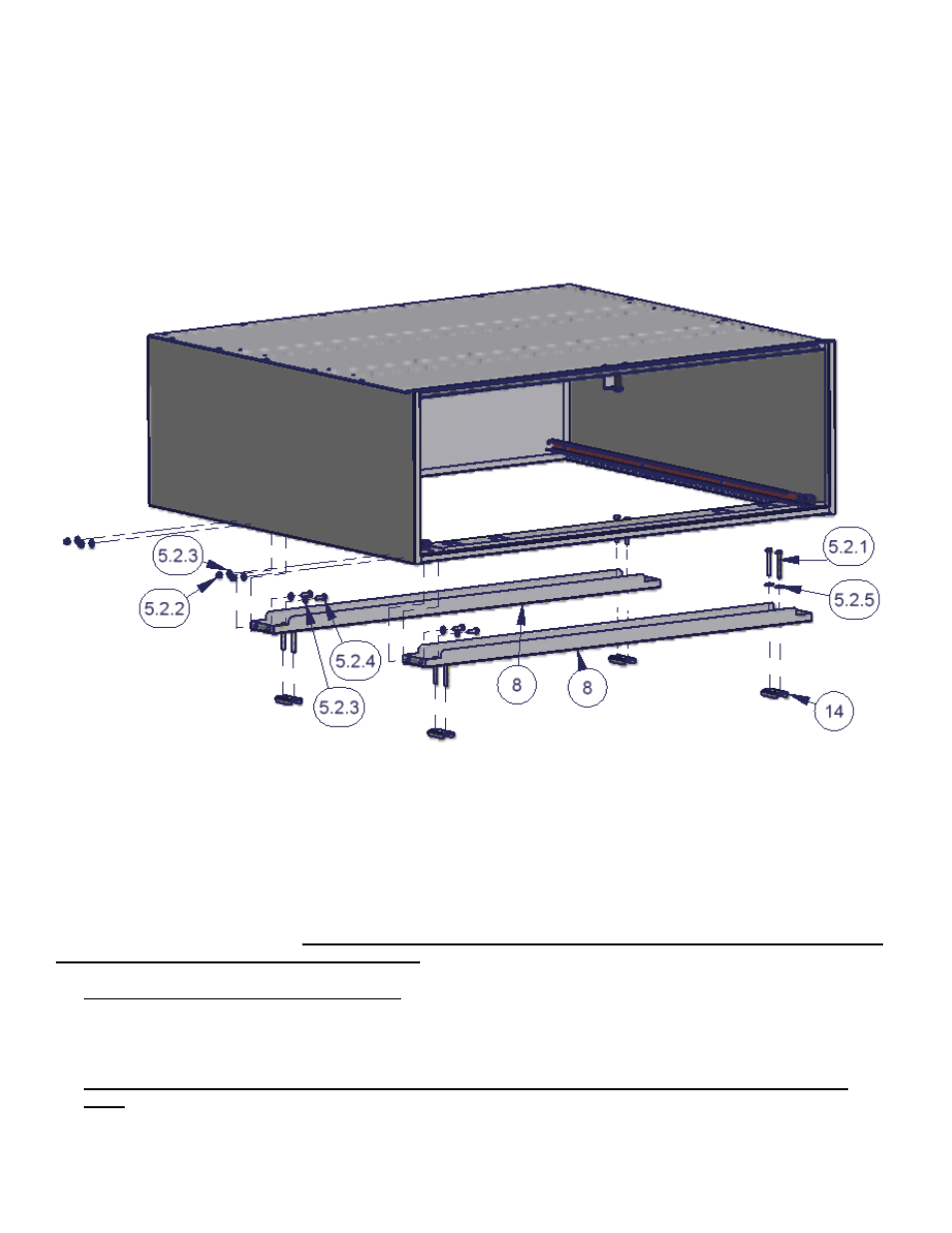
5. With the enclosure placed in the desired mounting location insert the (4) #14 clamps on the underside of the seat
anchors in the vehicle floor and
using a ½” socket, extension, and ratchet fasten them to the #8 mounting brackets
with the #5.2.1 Bolts and #5.2.5 Washers (#5.2.6 Bolts are a shorter length and may alternately be required for
mounting in some vehicles). Be sure the anchor point is completely enclosed between the B
olts and is “sandwiched”
between the #14 clamp and #8 mounting bracket and cannot slip out from behind it. Do not over tighten these bolts
or damage to the #8 mounting brackets will occur due to the necessary gap. (See Figure 3)
6. Insert the drawer and test the operation. Make sure there is clearance between the drawer handle and the rear
tailgate. Test to make sure that access to any important compartments in the floor or side panels are maintained.
FIGURE 3
ATTENTION:
FREQUENT LUBRICATION IS NECESSARY ON THE LOCKING SYSTEM
Th
e pushbutton lock contains an “O” ring seal to protect the interior from dust and water. If this mechanism is not
lubricated regularly it will become difficult to operate and it may not return to its home position preventing the key from
operating the lock. If this happens simply pull up on the pushbutton to manually bring it back to its home position.
Lubricate the pushbutton with a light lubricant such as silicone spray. The pushbutton may have to be periodically
disassembled and cleaned.
Required Periodic maintenance: Failure to perform periodic maintenance can result in the loss of access inside
the security enclosure and failure of components.
Lubrication is required for all moving parts. The schedule will vary depending on the level of usage and
environmental conditions. Once a month is a good starting point. Be sure to lubricate all friction points
completely. Use high temperature lithium grease. Key lubrication points are shown on the illustration below
for the latch system with the optional pushbutton combination lock. Some lube points in the illustration will
not be present on other latch systems. (See figure 4)
If the latch handle is removed or has been bumped out of alignment it will need to be adjusted correctly
again. The gap shown between the knob and the stop is critical and can vary slightly. If the gap is too small
the knob cannot be turned enough to unlock the latch. If the gap is too large then the knob can be turned
past its stop point which trips the internal clutch and will not unlock the latch. Adjust the handle so the gap