Top Flite TOPA0215 User Manual
Page 31
- 31 -
Install the Elevator, Rudder Pushrods
and Control Horns
❏
1. Locate the two 5/16" x 36" [7.9 x 914mm] wood
dowels. These will be the elevator and rudder pushrods.
Cut each of them to 24-1/2" [623mm] in length.
❏
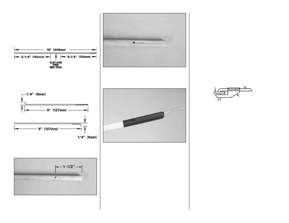
2. Locate two .074 x 12" [1.9 x 305mm] wires
threaded on one end. Cut them as shown in the sketch.
❏
3. Bend each of the wires as shown, making two
sets of wires as shown in the sketch.
❏
4. From each end of the dowel measure in 1-1/2"
[38mm]. Drill a 5/64" [2mm] hole on the mark, drilling
through the dowel.
❏
5. From the end of the dowel to the hole, cut a slot
the width of the hole.
❏
6. Insert the end of the rod with the 1/4" [6mm] bend
into the dowel. Insert the threaded rod into one end and
the un-threaded rod into the other. Apply a small
amount of thin CA to the rod and the dowel. Then allow
it to cure. Cut two pieces of heat shrink tubing to 2"
[51mm] in length, slide the heat shrink tubing over each
end of the dowel and then shrink it tight onto each of
the pushrod wires. Do this for both pushrods.
❏
7. If you would like the pushrods to match the rear
structure of the fuselage, paint or stain them to
match. If you will be painting them, mask off the heat
shrink tubing. Paint will not stick to it very well.
❏
8. Reference the plan to locate the position for the
nylon control horn on the bottom of the elevator.
Mark the location for the screw holes for the control
horn. Drill a 3/32" [2.4mm] hole through the elevator
on each of these marks then harden the holes with a
couple of drops of thin CA.
❏
9. Install the control horn onto the bottom of the
elevator. Install the two 2-56 machine screws through
the control horn and the control horn plate on the top
of the elevator.
❏
10. Repeat steps 9 and 10 for installing the control
horn on the rudder.
FasLink
2-56 (.074") Pushrod Wire
Servo Arn
❏
11. Put a silicone clevis keeper over the threaded
end of the elevator wire then install the clevis onto
the wire approximately 20 turns. Connect the clevis
to the control horn. Center the elevator and the servo
arm. Align the wire under the arm of the servo horn,
mark the location where it crosses the hole in the
arm and then bend the wire on the mark. Install the
wire onto the servo horn arm with a nylon Faslink.
Cut off any excess wire extending beyond the Faslink
more than 1/16" [1.6mm].
❏
12. Repeat step 11 for the rudder pushrod.