Carrier AQUAZONE PCV015-060 User Manual
Page 9
9
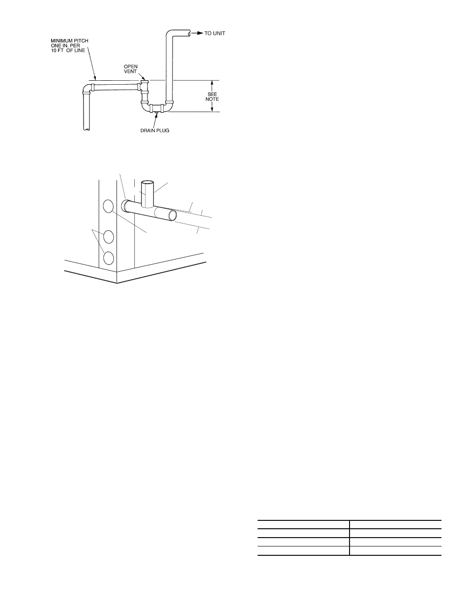
Each unit must be installed with its own individual vent and
means to flush or blow out the condensate drain line. Do not in-
stall units with a common trap or vent.
VENTING — Install a vent in the condensate line of any
application that may allow dirt or air to collect in the line. Con-
sider the following:
• Always install a vent where an application requires a
long horizontal run.
• Always install a vent where large units are working
against higher external static pressure and to allow
proper drainage for multiple units connected to the same
condensate main.
• Be sure to support the line where anticipated sagging from
the condensate or when “double trapping” may occur.
• If condensate pump is present on unit, be sure drain con-
nections have a check valve to prevent back flow of con-
densate into other units.
Step 7 — Pipe Connections —
Depending on the
application, there are 3 types of WSHP piping systems to
choose from: water loop, ground-water and ground loop. Refer
to Piping Section of Carrier System Design Manual for addi-
tional information.
All WSHP units use low temperature soldered female pipe
thread fittings for water connections to prevent annealing and
out-of-round leak problems which are typically associated with
high temperature brazed connections. Refer to Table 1 for con-
nection sizes. When making piping connections, consider the
following:
• Use a backup wrench when making screw connections to
unit to prevent internal damage to piping.
• Insulation may be required on piping to avoid condensa-
tion in the case where fluid in loop piping operates at
temperatures below dew point of adjacent air.
• Piping systems that contain steel pipes or fittings may
be subject to galvanic corrosion. Dielectric fittings may
be used to isolate the steel parts of the system to avoid
galvanic corrosion.
WATER LOOP APPLICATIONS — Water loop applications
usually include a number of units plumbed to a common pip-
ing system. Maintenance to any of these units can introduce air
into the piping system. Therefore, air elimination equipment
comprises a major portion of the mechanical room plumbing.
The flow rate is usually set between 2.25 and 3 gpm per ton
of cooling capacity. For proper maintenance and servicing,
pressure-temperature (P/T) ports are necessary for temperature
and flow verification.
In addition to complying with any applicable codes, consid-
er the following for system piping:
• Piping systems using water temperatures below 50 F
require
1
/
2
-in. closed cell insulation on all piping surfaces
to eliminate condensation.
• Avoid all plastic to metal threaded fittings due to the
potential to leak. Use a flange fitted substitute.
• Teflon tape thread sealant is recommended to minimize
internal fouling of the heat exchanger.
• Use backup wrench. Do not overtighten connections.
• Route piping to avoid service access areas to unit.
• Flush the piping system prior to operation to remove dirt
and foreign materials from the system.
GROUND-LOOP APPLICATIONS — Temperatures be-
tween 25 and 110 F and a cooling capacity of 2.25 to 3 gpm of
flow per ton is recommended. In addition to complying with
any applicable codes, consider the following for system piping:
• Limit piping materials to only polyethylene fusion in the
buried sections of the loop.
• Do not use galvanized or steel fittings at any time due to
corrosion.
• Avoid all plastic to metal threaded fittings due to the poten-
tial to leak. Use a flange fitted substitute.
• Do not overtighten connections.
• Route piping to avoid service access areas to unit.
• Use pressure-temperature (P/T) plugs to measure flow of
pressure drop.
INSTALLATION OF SUPPLY AND RETURN HOSE
KIT — Follow these piping guidelines.
1. Install a drain valve at the base of each supply and return
riser to facilitate system flushing.
2. Install shutoff/balancing valves and unions at each unit to
permit unit removal for servicing.
3. Place strainers at the inlet of each system circulating
pump.
4. Select the proper hose length to allow slack between con-
nection points. Hoses may vary in length by +2% to –4%
under pressure.
5. Refer to Table 2. Do not exceed the minimum bend radius
for the hose selected. Exceeding the minimum bend radi-
us may cause the hose to collapse, which reduces water
flow rate. Install an angle adapter to avoid sharp bends
in the hose when the radius falls below the required
minimum.
NOTE: Piping must comply with all applicable codes.
Table 2 — Metal Hose Minimum Bend Radii
HOSE DIAMETER (in.)
MINIMUM BEND RADII (in.)
1
/
2
2
1
/
2
3
/
4
4
1
5
1
/
2
NOTE: Trap should be deep enough to offset maximum unit static
difference. A 4-in. trap is recommended.
Fig. 10 — Trap Condensate Drain
a50-6261tf
Alternate
Condensate
Location
Vent
1/4” per foot
slope to drain
3/4” Copper FPT/PVC
Water
Connections
1/2”
1/2”
3/4” PVC
NOTE: Unit does not need to be sloped toward drain.
Fig. 11 — Vertical Condensate Connection