Carrier AQUAZONE PCV015-060 User Manual
Page 14
14
Fig
. 16
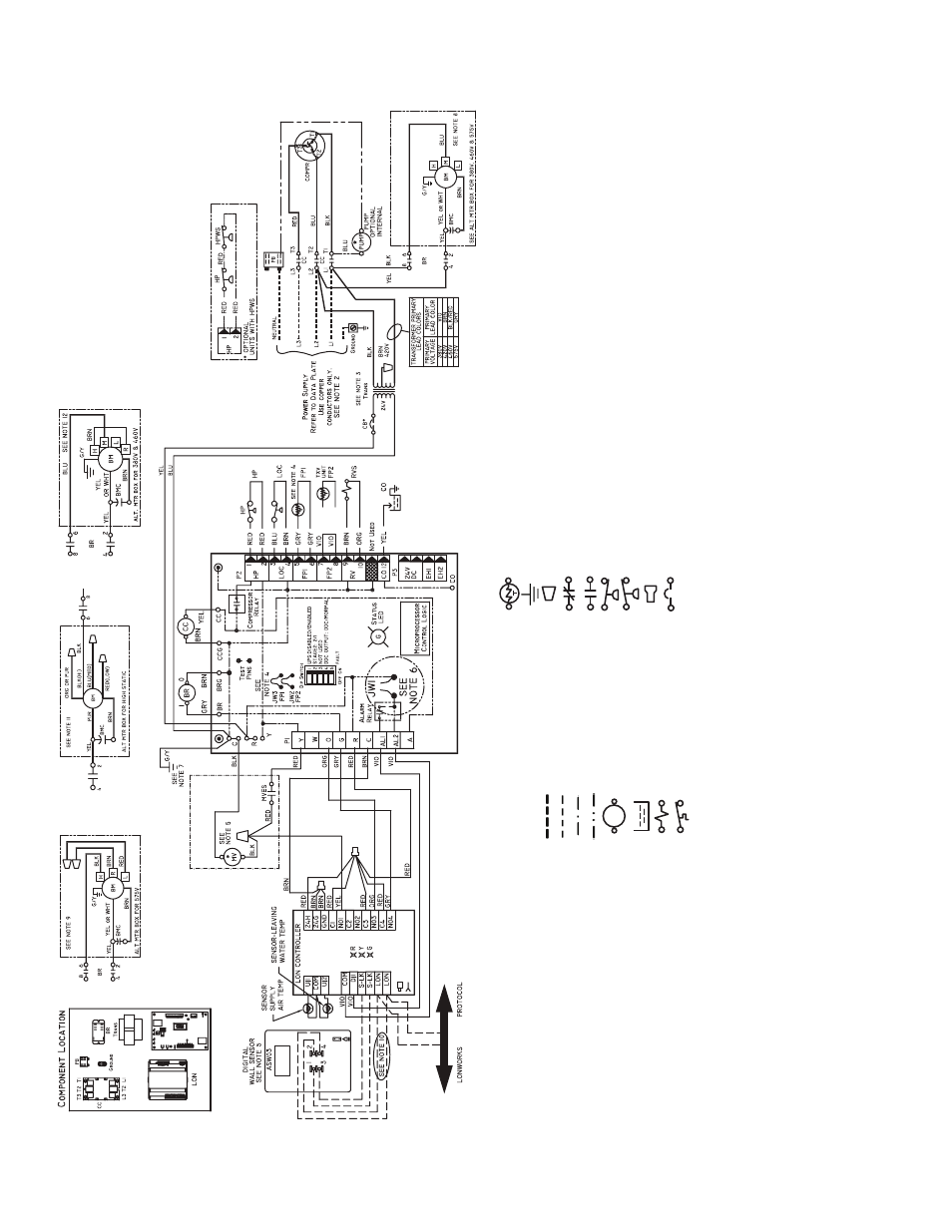
— 50PCH,PCV Un
it
s wi
th
Compl
e
te C and LO
N Cont
ro
ll
er (
460
V)
C
omplet
e C
a50-8493
LE
GEND
AL
—
A
lar
m Rela
y
Co
nta
c
ts
BM
—
Blo
w
e
r M
o
to
r
BMC
—
B
lo
w
er Mot
o
r Capacit
or
BR
—
B
lo
w
er Rela
y
CAP
—
Co
mpressor Capacit
or
CB
—
Cir
c
u
it Br
eak
er
CC
—
Co
mpressor Cont
acto
r
CO
—
S
ensor
, Co
nden
sa
te
Ov
er
flo
w
FP1
—
S
ensor
, L
o
w T
e
mpe
rat
ure
P
rot
ectio
n
,
W
a
te
r
Coil
FP2
—
S
ensor
, L
o
w T
e
mpe
rat
ure
P
rot
ectio
n
,
Ai
r Coi
l
HP
—
Hig
h-Pr
ess
u
re Switc
h
HPW
S
—
Hig
h-Pr
ess
u
re W
a
te
r
S
witch
JW
1
—
Cli
ppab
le Field Se
lecti
on J
u
mper
LO
C
—
L
o
ss
of
Ch
arge
Pr
essu
re
Swit
ch
LO
N
—
L
o
cal Oper
at
ing Net
w
or
k
MV
—
Mo
tor
iz
ed V
a
lv
e
MV
ES
—
Mo
tor
iz
ed V
a
lv
e En
d
S
witch
NEC
—
Na
tio
nal Elect
rical
Cod
e
*Op
tio
nal Wir
ing.
P1
—
F
ield Wir
ing T
e
rm
ina
l
B
loc
k
RV
S
—
Re
v
e
rsin
g V
a
lv
e
Sole
noid
TRANS
—
T
ransf
o
rm
er
TXV
—
T
h
er
most
at
ic E
x
p
ansion
V
a
lv
e
F
ield
Line
V
o
lt
age
Wir
ing
F
ield Lo
w V
o
lt
ag
e Wir
in
g
Pr
in
te
d C
ircuit
T
ra
c
e
O
p
ti
o
n
a
l Wi
ri
ng
Rela
y
/Contactor Coil
Conden
sa
te
P
a
n
Sole
noid Coil
T
e
mper
atu
re Swit
ch
T
h
er
m
ist
or
G
roun
d
Wi
re N
u
t
Rel
a
y Cont
acts - N
.C
.
Rel
a
y Cont
acts - N
.O
.
L
o
w Pr
es
su
re
Sw
it
ch
Hig
h P
ressure
Switch
S
p
lice Cap
Cir
c
u
it Bre
a
k
e
r
NO
TES
:
1.
Co
m
p
ressor and b
lo
w
er mot
o
r th
er
mal
ly pr
ote
c
ted int
e
rnally
.
2.
A
ll w
ir
ing
t
o
th
e unit
m
u
st co
mply
wi
th NEC and local
code
s
.
3.
T
ransf
o
rm
e
r
is
wir
ed
to
460 v BLK
/RED lead f
o
r 460-
3-60
unit
s
. T
rans-
fo
rm
er is ener
g
y
limit
ing or ma
y ha
v
e
circui
t bre
a
k
e
r.
4.
FP
1
ther
m
ist
or pro
v
ide
s
lo
w
te
mper
at
ure prot
ect
ion f
o
r w
a
ter
.
Wh
en
u
s
ing ant
ifr
eez
e so
lut
ions
, cut JW3 jumpe
r.
5.
Re
fe
r to micropr
ocesso
r
cont
ro
l, LON,
or
ther
most
at
in
stal
lat
ion
in
str
u
ctio
ns f
o
r wi
ri
ng
to
th
e un
it.
Wire
“N01”
fr
om LO
N to
“Y1”
Com-
p
let
e
C when a mot
o
ri
z
ed v
a
lv
e
is
not
used.
Lo
w v
o
lta
ge wir
in
g
m
u
st
b
e
Class 1
and
v
o
lt
age
ra
ti
ng
equa
l t
o
o
r g
reat
er
tha
n
un
it
supply
vo
lt
a
g
e
.
6.
F
a
ct
or
y
cu
t
JW1
jump
er
. Dr
y
co
nta
c
t wil
l be
a
v
ail
a
b
le be
tw
e
en A
L1 a
n
d
A
L2.
7.
T
ransf
o
rm
e
r secon
dar
y g
round
via
g
reen
wire
wit
h y
e
llo
w st
ri
p
f
rom
“C”
te
rm
in
a
l
to
co
nt
ro
l bo
x.
8.
F
a
n
mot
o
rs
a
re f
a
cto
ry w
ired f
o
r mediu
m
spee
d. F
o
r
hig
h
o
r
lo
w speed
,
re
mo
v
e
BLU wir
e fr
om f
a
n
moto
r speed
ta
p “M” a
nd conn
ect t
o
“H”
f
o
r
h
igh speed
or
“L
” f
o
r lo
w sp
eed.
9.
F
o
r l
o
w
sp
eed,
re
mo
v
e
BLK
wire f
rom
BR “6
” and
rep
lace wit
h RED
.
Co
nnect
B
L
K and BRN wires tog
e
ther
.
1
0
.
O
pt
ional
LON wire
s
. Only conn
ect
if
LO
N co
nnect
ion is de
si
red at
t
h
e
w
a
ll sensor
.
1
1
.
F
or b
lo
w
er
mot
o
rs wit
h le
ads
. F
o
r me
dium o
r lo
w spe
ed,
disconn
ect
B
L
K wire fr
om
B
R
“6”
. Conne
ct
BLK and
O
R
G
/P
UR
wire
toget
her
.
Co
nnect
RED f
o
r
lo
w or BLU f
o
r med
ium to BR
“6
”.
1
2
.
B
lo
w
e
r mot
o
r f
a
ct
or
y
wir
ed to
me
dium speed
. F
o
r lo
w
spe
ed remo
v
e
B
L
U wir
e f
rom
medium
ta
p a
nd
co
nnect
t
o
lo
w
speed
ta
p
. F
o
r h
igh
spe
ed,
remo
v
e
BLU wir
e fr
om e
x
isit
ing spe
ed t
ap an
d remo
v
e
BRN
ju
mper wire
f
ro
m
h
igh speed
t
a
p
. Conn
ect BL
U
wir
e to hi
gh speed
t
a
p
.
T
a
p
e
off
unconn
ected
e
nd of BRN jumpe
r.
1
3
.
T
he
4
60-v uni
ts using an
i
n
te
rnal
secon
dar
y
p
u
mp will req
u
ire a ne
u-
tr
a
l wire
fro
m
th
e suppl
y
sid
e
in
orde
r to
f
eed
th
e accessor
y
wi
th
265-v
.