Replacing the wshp open controller’s bat- tery, Thermistor, Control sensors – Carrier AQUAZONE PCV015-060 User Manual
Page 40: Wshp open controller
40
1. Shut off unit main power supply.
2. Loosen bolts on mounting bracket so that fan belt can be
removed.
3. Loosen and remove the 2 motor mounting bracket bolts
on left side of bracket.
4. Slide motor/bracket assembly to extreme right and lift out
through space between fan scroll and side frame. Rest
motor on a high platform such as a step ladder. Do not
allow motor to hang by its power wires.
Replacing the WSHP Open Controller’s Bat-
tery —
The WSHP Open controller’s 10-year lithium
CR2032 battery provides a minimum of 10,000 hours of data
retention during power outages.
NOTE: Power must be ON to the WSHP Open controller
when replacing the battery, or the date, time and trend data will
be lost.
1. Remove the battery from the controller, making note of
the battery's polarity.
2. Insert the new battery, matching the battery's polarity
with the polarity indicated on the WSHP Open controller.
TROUBLESHOOTING
(Fig. 34 and 35, and Table 29)
When troubleshooting problems with a WSHP, consider the
following.
Thermistor —
A thermistor may be required for single-
phase units where starting the unit is a problem due to low
voltage. See Fig. 34 for thermistor nominal resistance.
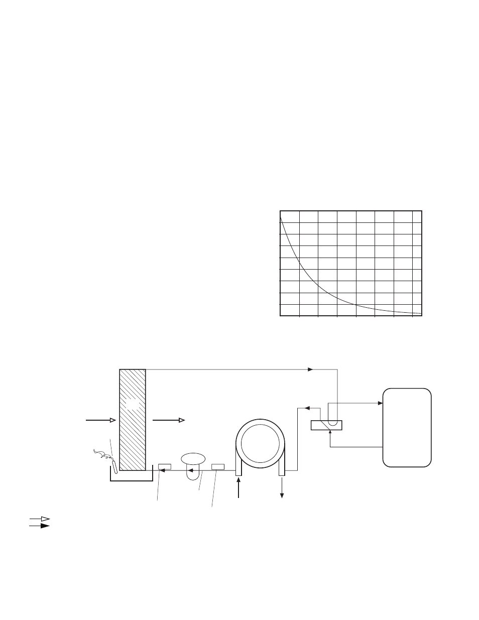
Control Sensors —
The control system employs 2 nom-
inal 10,000 ohm thermistors (FP1 and FP2) that are used for
freeze protection. Be sure FP1 is located in the discharge fluid
and FP2 is located in the air discharge. See Fig. 35.
WSHP Open Controller —
With the WSHP Open con-
troller option, the 100 most recent alarms can be viewed using
the BACview
6
alarm status and alarm history.
To view the alarms:
1. Navigate to the Alarm Status screen from the Home
screen using the arrow softkeys. The screen will display
the current alarm status, either normal or Alarm, and al-
low for scrolling through the unit’s alarm status.
2. From the Alarm Status screen, press the Alarm softkey to
view the 100 most recent alarms which are labeled with
date and time for easy reference.
NOTE: Active faults can be viewed by scrolling down,
these faults indicate a possible bad sensor or some condi-
tion which may not merit an alarm.
3. To view alarms which have been corrected, scroll down
through the Alarm screen to Return Top Normal screen.
NOTE: Alarms are automatically reset once alarm con-
dition has been corrected.
See Table 29 for possible alarm cause and solution.
0.0
10.0
20.0
30.0
40.0
50.0
60.0
70.0
80.0
90.0
0.0
20.0
40.0
60.0
80.0
100.0
120.0
140.0
Temperature (degF)
Resistance (kOhm)
Fig. 34 — Thermistor Nominal Resistance
a50-8163
SUCTION
COMPRESSOR
DISCHARGE
COAX
EXPANSION
VALVE
FP2
FP1
LIQUID
LINE
WATER IN
WATER OUT
CONDENSATE
OVERFLOW
(CO)
AIR COIL
FREEZE
PROTECTION
WATER
COIL
PROTECTION
THERMISTOR
(
°F)
(
°F)
AIR
COIL
AIRFLOW
AIRFLOW
LEGEND
Fig. 35 — FP1 and FP2 Thermistor Location
COAX — Coaxial Heat Exchanger
Airflow
Refrigerant Liquid Line Flow