Carrier AQUAZONE PCV015-060 User Manual
Page 12
12
NO
TES
:
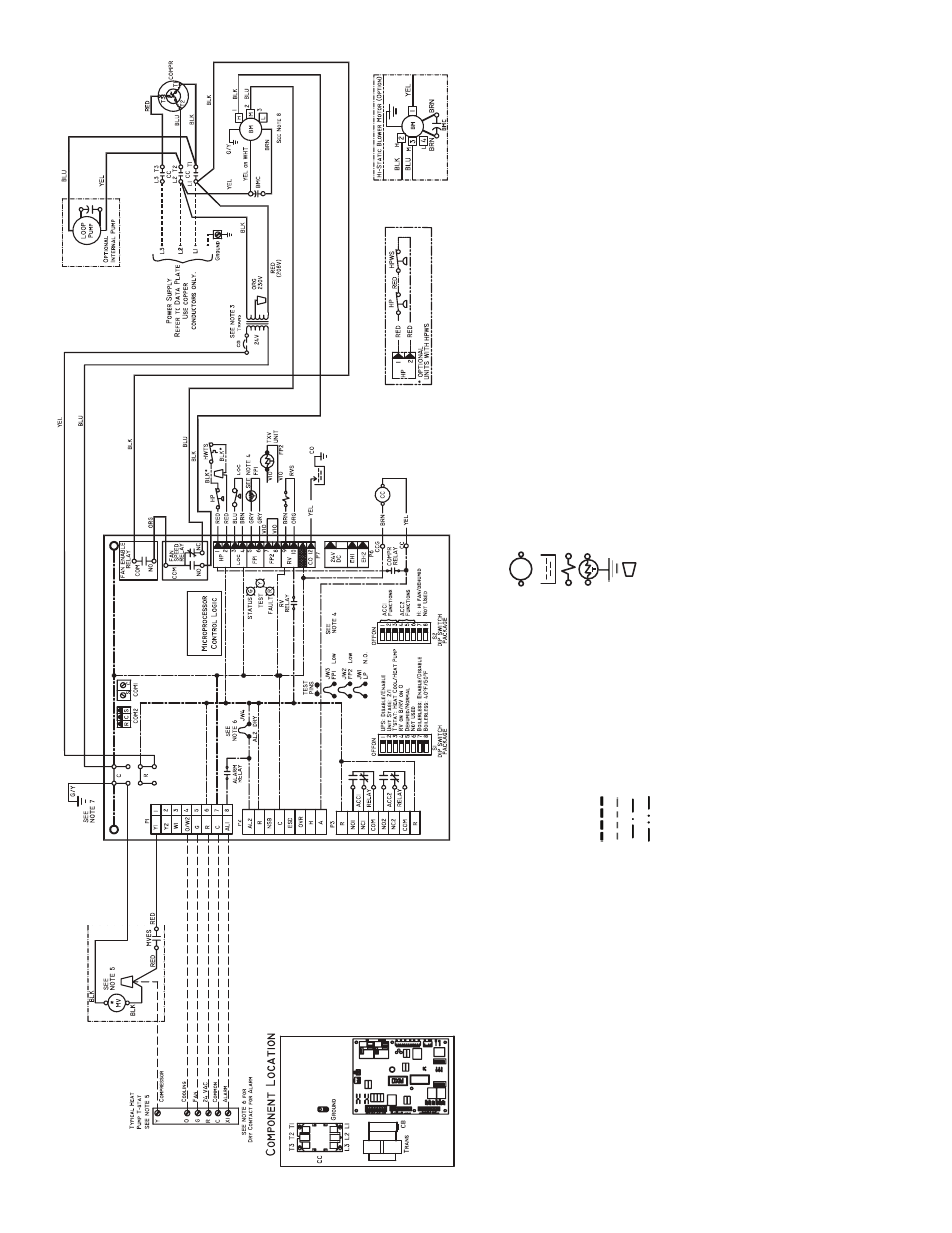
1.
Co
m
p
ressor th
er
mal
ly pro
te
c
ted int
e
rnally
.
2.
A
ll w
ir
ing
t
o
th
e unit
m
u
st comply
wi
th NEC and local
code
s
.
3.
T
ransf
o
rm
e
r is wire
d
t
o
208
-v
RED lea
d
f
o
r 208-
3-60
un
its
.
F
o
r 230-
3-60,
s
witch RED and O
R
G
l
eads at
L
1
a
nd insula
te RED lea
d
. T
ran
sf
or
mer
is
e
nerg
y
l
imiti
ng or ma
y ha
v
e
circuit
brea
k
e
r.
4.
FP
1
ther
mist
or
pro
v
id
es
fr
eez
e prot
ecti
on f
o
r w
a
te
r.
Wh
en using ant
i-
fr
e
e
z
e
so
lu
tio
n
s
,
cu
t J
W
3
jum
p
e
r.
5.
Re
fe
r
to
micropr
ocesso
r cont
ro
l,
LON,
o
r t
her
mostat
i
n
stal
lat
ion
instr
u
c-
ti
on
s f
o
r wir
in
g t
o
th
e unit
. Wire “Y
” fr
om th
er
most
at
to “
Y
1” Del
u
x
e
D
when
mot
o
ri
z
e
d
v
a
lv
e
is not
used
. Th
er
most
at
wir
in
g m
u
st
be
C
lass
1
an
d v
o
lt
age
r
a
ti
ng
equal
t
o
o
r g
rea
ter
t
han
uni
t
su
pply
v
o
lt
ag
e
.
Heat
/coo
l
ther
mo
st
at
s
n
o
t compat
ib
le with
mot
o
ri
z
e
d w
a
te
r
v
a
lv
e
.
6.
24
-v alar
m signa
l sho
w
n.
F
o
r dr
y ala
rm cont
act
,
cu
t JW4
jumpe
r an
d dr
y
cont
act
will be
a
v
a
ilab
le bet
w
een
A
L1 and AL
2.
7.
T
ran
sf
or
mer
seconda
ry
g
rou
nd
vi
a g
reen
wire
wit
h y
e
llo
w str
ipe
f
rom “
C
”
te
rm
in
al to cont
rol bo
x.
8.
Bl
o
w
er mot
o
r is f
a
cto
ry wired f
o
r medium an
d high
spe
eds
. F
o
r
a
n
y ot
he
r
combin
at
ion o
f spe
eds
, a
tt
a
ch b
lac
k wire
to
th
e hig
her o
f t
h
e
tw
o
desire
d
spee
d
taps and
t
he b
lue wire to
t
he lo
w
e
r
o
f th
e
tw
o desir
ed sp
eed t
aps
.
a50-849
1
Fig. 1
4
—
50
PCH
,PCV
Unit
s
wit
h De
lux
e
D Contr
o
lle
r, Three
-P
ha
s
e
(2
08
/2
30
V)
De
lu
xe
D
LE
G
E
N
D
R
e
la
y/
Cont
act
o
r C
o
il
C
o
nden
sa
te P
a
n
Solen
o
id Coil
T
h
er
mist
or
Grou
nd
Wire Nut
*O
p
tio
nal.
AL
—
A
lar
m Rela
y
Con
tacts
BM
—
Blo
w
e
r M
o
to
r
BMC
—
B
lo
w
er Mot
o
r Capacit
or
CAP
—
Comp
ressor C
a
pacit
or
CB
—
Circui
t Bre
a
k
e
r
CC
—
Comp
ressor C
o
nt
actor
CO
—
S
ensor
, Con
densat
e
Ov
erf
lo
w
FP1
—
S
ensor
,
Lo
w T
e
mper
at
ure Pr
ote
c
ti
on
W
a
te
r Coil
FP2
—
S
ensor
,
Lo
w T
e
mper
at
ure Pr
ote
c
ti
on
A
ir C
o
il
HP
—
High
-Pre
s
sur
e
Switch
HPWS
—
High
-Pre
s
sur
e
W
a
ter
Switch
HWTS
—
High
L
e
a
v
in
g W
a
te
r
T
e
mper
at
ure
Swit
ch
JW1
—
J
u
m
p
er
, A
lar
m
LOC
—
Loss o
f
Charg
e
Pressure S
witch
MV
—
Mot
o
ri
z
ed V
a
lv
e
MV
ES
—
Mot
o
ri
z
ed V
a
lv
e
E
nd Swit
ch
NE
C
—
Nati
onal El
ectr
ica
l
Co
de
P1
—
Field Wir
ing T
e
rm
ina
l
B
loc
k
RV
S
—
Re
v
e
rsin
g V
a
lv
e
Sole
noid
TRANS
—
T
ransf
o
rm
er
TXV
—
Ther
mo
st
at
ic E
x
p
ansion
V
a
lv
e
Field
Lin
e
V
o
lt
age
Wi
ri
ng
Field Lo
w V
o
ltag
e Wir
in
g
Pr
in
te
d C
ircuit
T
ra
c
e
Opt
ion
al Wir
in
g