Carrier AQUAZONE PCV015-060 User Manual
Page 8
8
Side to Back Discharge Conversion
1. Remove screws to free the top and discharge panels. See
Fig. 5.
2. Remove the access panel and set aside.
3. Lift the discharge panel from side of unit and rotate it to
back using care not to damage blower wiring.
4. Check blower wire routing and connections for undue
tension or contact with sheet metal edges. Re-route if
necessary.
5. Check refrigerant tubing for contact with other compo-
nents. Adjust if necessary.
6. Reinstall top panel using screws set aside in Step 1.
NOTE: Location for some screws at bottom of discharge panel
may have to be changed.
7. Manually spin fan wheel to check for obstructions.
Adjust for any obstruction found.
8. Replace access panel.
Back to Side Discharge Conversion — Follow instructions
above for Side to Back Discharge Conversion, noting the
panels would be reversed.
Step 4 — Mount the Unit
HORIZONTAL UNITS (50PCH) — Horizontal units should be
mounted using the factory-installed hangers. Proper attachment
of hanging rods to building structure is critical for safety. See
Fig. 2 and 7. Rod attachments must be able to support the
weight of the unit. See Table 1 for unit operating weights.
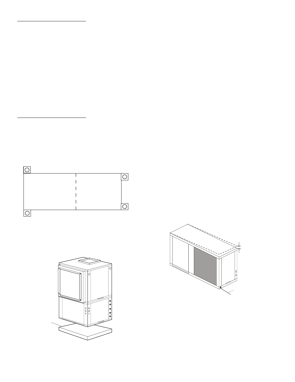
VERTICAL UNITS (50PCV) — Vertical units are available in
left or right return air configurations. See Fig. 3. Mount the unit
on a vibration absorption pad slightly larger than the entire base
to minimize vibration transmission. It is not necessary to mount
the unit on the floor. See Fig. 8.
NOTE: Some codes require the use of a secondary drain pan
under vertical units. Check local codes for more information.
Step 5 — Check Duct System —
Size the duct sys-
tem to handle the design airflow quietly.
NOTE: Depending on the unit, the fan wheel may have a ship-
ping support installed at the factory. This must be removed
before operating unit.
SOUND ATTENUATION — To eliminate the transfer of
vibration to the duct system, a flexible connector is recom-
mended for both discharge and return air duct connections on
metal duct systems. The supply and return plenums should in-
clude internal duct liner of fiberglass or be made of duct board
construction to maximize sound attenuation of the blower.
Installing the WSHP unit to uninsulated ductwork in an uncon-
ditioned space is not recommended since it will sweat and
adversely affect the unit’s performance.
To reduce air noise, at least one 90-degree elbow could be
included in the supply and return air ducts, provided system
performance is not adversely impacted. The blower speed can
also be changed in the field to reduce air noise or excessive air-
flow, provided system performance is not adversely impacted.
EXISTING DUCT SYSTEM — If the unit is connected to
existing ductwork, consider the following:
• Verify that the existing ducts have the proper capacity to
handle the unit airflow. If the ductwork is too small,
install larger ductwork.
• Check existing ductwork for leaks and repair as
necessary.
NOTE: Local codes may require ventilation air to enter the
space for proper indoor air quality. Hard-duct ventilation may
be required for the ventilating air supply. If hard ducted venti-
lation is not required, be sure that a proper air path is provided
for ventilation air to unit to meet ventilation requirement of the
space.
Step 6 — Install Condensate Drain
HORIZONTAL UNITS (50PCH) — Slope the unit toward
the drain at a
1
/
4
in. drop at drain end. See Fig. 9. If it is not pos-
sible to meet the required pitch, install a condensate pump at
the unit to pump condensate to building drain.
Horizontal units are not internally trapped, therefore an ex-
ternal trap is necessary. Install each unit with its own individual
trap and means to flush or blow out the condensate drain line.
Do not install units with a common trap or vent. For typical
condensate connections see Fig. 10.
NOTE: Never use a pipe size smaller than the connection.
VERTICAL UNITS (50PCV) — Each unit uses a condensate
hose inside all cabinets as a trapping loop, therefore an external
trap is not necessary. See Fig. 11.
Fig. 7 — Horizontal Hanger Bracket
(Factory Installed)
COMPRESSOR
SECTION
AIR HANDLER
SECTION
a50-8489
Vibration
Absorption
Pad
Fig. 8 — 50PCV Units Mounted with
Vibration Absorption Pad
Fig. 9 — Horizontal Unit Pitch
1/4” Pitch for
Drainage
Drain Connection
Pitch Toward
Drain