Service, Filters, Water coil – Carrier AQUAZONE PCV015-060 User Manual
Page 38: Condensate drain pans, Refrigerant system, Compressor, Fan motors, Condensate drain cleaning, Air coil cleaning
38
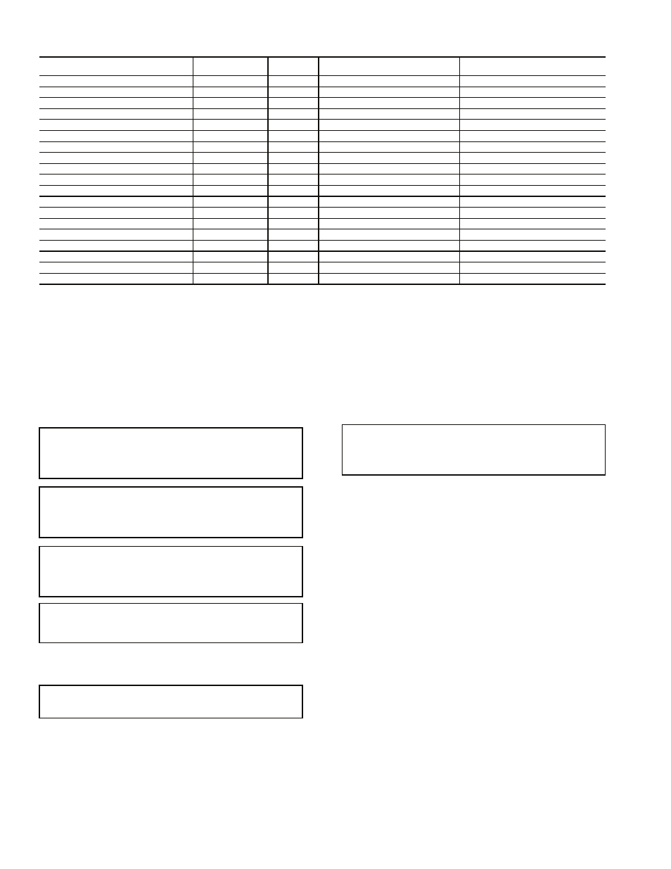
Table 28 — Aquazone Deluxe D Control Current LED Status and Alarm Relay Operations
LEGEND
NOTES:
1. If there is no fault in memory, the Fault LED will flash code 1.
2. Codes will be displayed with a 10-second Fault LED pause.
3. Slow flash is 1 flash every 2 seconds.
4. Fast flash is 2 flashes every 1 second.
5. EXAMPLE: “Flashing Code 2” is represented by 2 fast flashes followed by a
10-second pause. This sequence will repeat continually until the fault is
cleared.
SERVICE
Perform the procedures outlined below periodically, as
indicated.
Filters —
Filters must be clean for maximum performance.
Inspect filters every month under normal operating conditions.
Replace when necessary.
Water Coil —
Keep all air out of the water coil. Check
open loop systems to be sure the well head is not allowing air
to infiltrate the water line. Always keep lines airtight.
Inspect heat exchangers regularly, and clean more frequent-
ly if the unit is located in a “dirty” environment. Keep the heat
exchanger full of water at all times. Open-loop systems should
have an inverted P trap placed in the discharge line to keep
water in the heat exchanger during off cycles. Closed-loop
systems must have a minimum of 15 psig during the summer
and 40 psig during the winter. Generally, the higher the water
flow through the bail, the lower the chance for sealing.
Check P trap frequently for proper operation.
Condensate Drain Pans —
Check condensate drain
pans for algae growth twice a year. If algae growth is apparent,
consult a water treatment specialist for proper chemical treat-
ment. Applying an algaecide every three months will typically
eliminate algae problems in most locations.
Refrigerant System —
Verify air and water flow rates
are at proper levels before servicing. To maintain sealed circuit-
ry integrity, do not install service gauges unless unit operation
appears abnormal.
Check to see that unit is within the superheat and subcool-
ing temperature ranges shown in Tables 16-22. If the unit is not
within these ranges, recover and reweigh in refrigerant charge.
Compressor —
Conduct annual amperage checks to en-
sure that amp draw is no more than 10% greater than indicated
on the serial plate data.
Fan Motors —
All units have lubricated fan motors. Fan
motors should never be lubricated unless obvious, dry opera-
tion is suspected. Periodic maintenance oiling is NOT recom-
mended as it will result in dirt accumulating in the excess oil
and cause eventual motor failure. Conduct annual dry opera-
tion check and amperage check to ensure amp draw is no more
than 10% greater than indicated on serial plate data.
Condensate Drain Cleaning —
Clean the drain line
and unit drain pan at the start of each cooling season. Check
flow by pouring water into drain. Be sure trap is filled to main-
tain an air seal.
Air Coil Cleaning —
Remove dirt and debris from evap-
orator coil as required by condition of the coil. A 10% solution
DESCRIPTION
STATUS LED
(Green)
TEST LED
(Yellow)
FAULT LED (Red)
ALARM RELAY
Normal Mode
On
Off
Flash Last Fault Code in Memory
Open
Normal Mode with PM
On
Off
Flashing Code 8
Cycle (closed 5 sec, open 25 sec, …)
Deluxe D Control is non-functional
Off
Off
Off
Open
Test Mode
—
On
Flash Last Fault Code in Memory
Cycling Appropriate Code
Night Setback
Flashing Code 2
—
Flash Last Fault Code in Memory
—
ESD
Flashing Code 3
—
Flash Last Fault Code in Memory
—
Invalid T-stat Inputs
Flashing Code 4
—
Flash Last Fault Code in Memory
—
No Fault in Memory
On
Off
Flashing Code 1
Open
HP Fault
Slow Flash
Off
Flashing Code 2
Open
LP Fault
Slow Flash
Off
Flashing Code 3
Open
FP1 Fault
Slow Flash
Off
Flashing Code 4
Open
FP2 Fault
Slow Flash
Off
Flashing Code 5
Open
CO Fault
Slow Flash
Off
Flashing Code 6
Open
Over/Under Voltage
Slow Flash
Off
Flashing Code 7
Open (closed after 15 minutes)
HP Lockout
Fast Flash
Off
Flashing Code 2
Closed
LP Lockout
Fast Flash
Off
Flashing Code 3
Closed
FP1 Lockout
Fast Flash
Off
Flashing Code 4
Closed
FP2 Lockout
Fast Flash
Off
Flashing Code 5
Closed
CO Lockout
Fast Flash
Off
Flashing Code 6
Closed
CO
— Condensate Overflow
HP
—
High Pressure
ESD
— Emergency Shutdown
LP
—
Low Pressure
FP
— Freeze Protection
PM
—
Performance Monitor
IMPORTANT: When a compressor is removed from this
unit, system refrigerant circuit oil will remain in the com-
pressor. To avoid leakage of compressor oil, the refrigerant
lines of the compressor must be sealed after it is removed.
IMPORTANT: All refrigerant discharged from this unit
must be recovered without exception. Technicians must fol-
low industry accepted guidelines and all local, state and fed-
eral statutes for the recovery and disposal of refrigerants.
IMPORTANT: To avoid the release of refrigerant into the
atmosphere, the refrigerant circuit of this unit must only be
serviced by technicians who meet local, state and federal
proficiency requirements.
IMPORTANT: To prevent injury or death due to electrical
shock or contact with moving parts, open unit disconnect
switch before servicing unit.
IMPORTANT: Units should never be operated with-
out a filter.
IMPORTANT: To avoid fouled machinery and extensive
unit clean-up, DO NOT operate units without filters in
place. DO NOT use equipment as a temporary heat source
during construction.