Carrier AQUAZONE PCV015-060 User Manual
Page 13
13
NO
TES:
1.
Compre
ssor
t
her
mally prot
ect
ed int
e
rn
a
lly
.
2.
All
wir
ing t
o
t
he un
it m
u
st
compl
y
wit
h N
E
C
a
nd local co
des
.
3.
T
ran
sf
o
rmer is wired
t
o
460
-v
B
L
K/
RED lead
f
o
r 460-
3-60
u
n
it
s or
5
75-v
GR
Y lea
d
f
o
r 575
-3-6
0 unit
s
. T
ransf
o
rm
er is
e
nerg
y
limit
ing or ma
y
h
a
v
e
circuit
b
reak
e
r.
4.
FP1 t
h
e
rmisto
r pro
v
id
es lo
w t
e
mper
atu
re p
rot
ectio
n
f
o
r w
a
ter
. Wh
en
using
an
tif
ree
z
e
solut
ion
s
, cut
JW3
ju
mper
.
5.
Ref
e
r
to
microp
rocessor c
o
nt
rol,
L
O
N,
o
r the
rmostat in
s
talla
tio
n
instr
u
c-
ti
ons f
o
r wir
ing to
t
h
e
u
n
it
. Wire
“Y
” fr
om the
rmost
at t
o
“Y1”
De
lux
e
D
when
moto
ri
z
ed v
a
lv
e
is
not
used.
Ther
mostat
wir
ing m
u
st b
e
Class 1
and
v
o
lt
age
ra
tin
g
eq
ual
to
or
g
reat
er
tha
n
u
n
it
supp
ly
v
o
lt
age
. Heat
/c
o
o
l
ther
mo
st
at
s no
t
compat
ib
le
with
mot
o
ri
z
e
d w
a
te
r
v
a
lv
e
.
6.
24
-v
alar
m si
gnal
sh
o
w
n
. F
o
r d
ry al
ar
m cont
act
, cut
JW4 j
u
mper
and d
ry
cont
act
will be
a
v
a
ilab
le bet
w
een
A
L1 and AL2
.
7.
T
ran
sf
or
mer
seconda
ry
g
ro
und
vi
a g
reen
wire
wit
h y
e
llo
w st
ri
p
e
f
rom
“C”
te
rm
in
al to cont
rol bo
x.
8.
Blo
w
er mot
o
r is f
a
ct
or
y wir
ed f
o
r m
e
dium an
d hig
h
sp
eeds
.
F
o
r an
y
ot
her
combina
tio
n of
spe
eds
,
att
a
ch
b
la
c
k
wire t
o
th
e hig
her
of
th
e t
w
o
de
sir
ed spe
ed t
aps at
t
he
moto
r.
Att
a
ch t
h
e
b
lu
e
wire
to
t
he lo
w
e
r of
t
h
e
tw
o desired
spee
d tap
s
.
9.
Blo
w
er mot
o
r is f
a
ct
or
y wired
f
o
r
high
and
lo
w spee
ds
. No
ot
her
co
mbi-
na
tio
n
o
f speed
s is
a
v
ailab
le
.
10.
The 46
0-v unit
s
using an
int
e
rn
a
l s
e
c
o
ndar
y pump will
requi
re a ne
utr
a
l
wire
f
rom th
e su
pply sid
e
i
n
o
rder
t
o
f
eed
t
he accesso
ry with
26
5-v
.
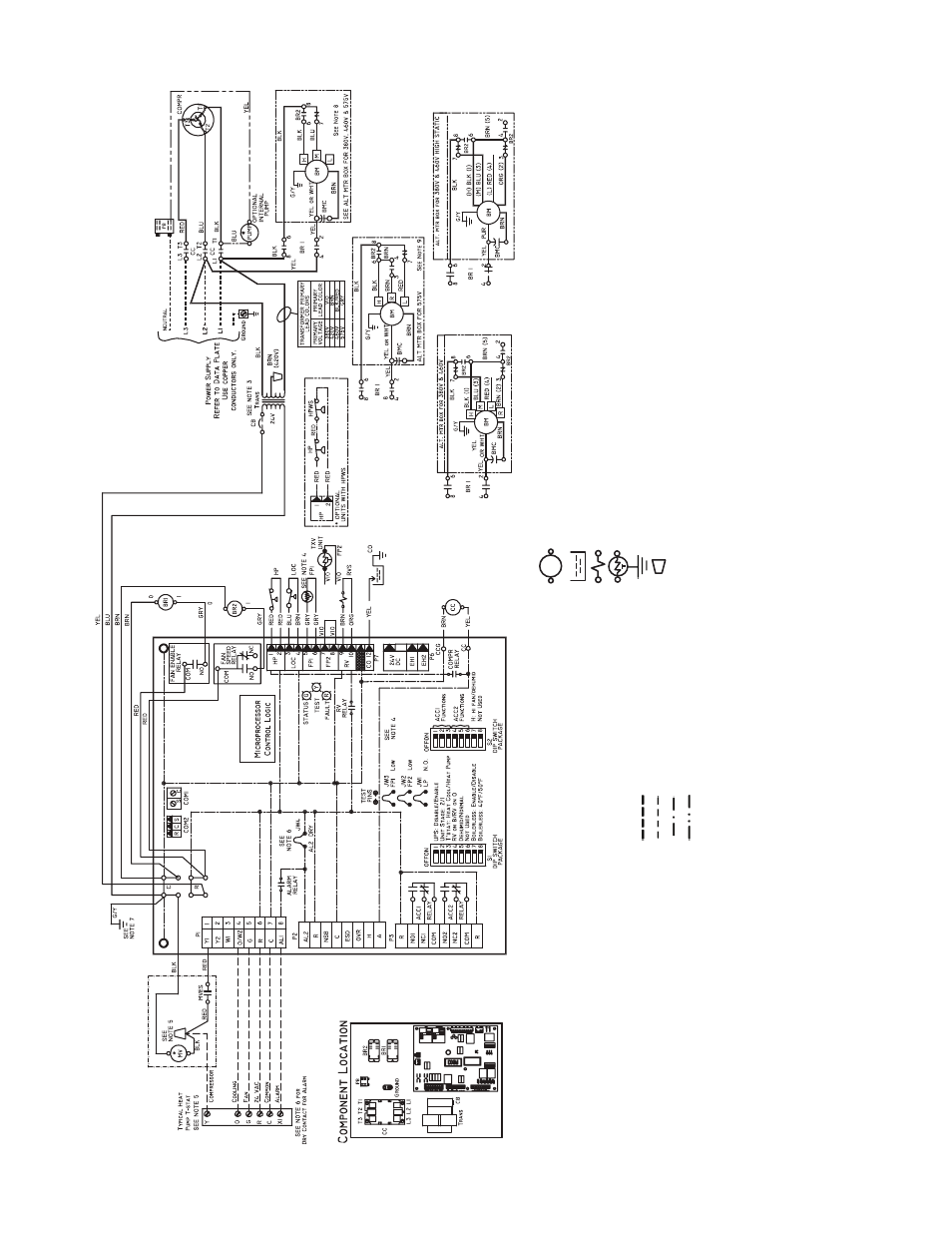
a50-8492
Fi
g.
1
5
— 50
PCH,
PCV Un
it
s wi
th
De
lu
xe D
Con
tr
o
ll
e
r, Th
ree
-Pha
se (
460
V)
D
elux
e
D
LEG
E
ND
Rela
y/Contactor
Coi
l
Con
densat
e P
a
n
S
o
leno
id Coil
T
h
er
m
ist
or
G
roun
d
Wir
e
Nu
t
*O
pt
ional
.
AL
—
A
lar
m Rela
y
Co
nta
c
ts
BM
—
Blo
w
e
r M
o
to
r
BMC
—
B
lo
w
er Mot
o
r Capa
cit
o
r
BR
—
B
lo
w
er Rela
y
CAP
—
Co
mpressor Capacit
or
CB
—
Cir
c
u
it Br
eak
er
CC
—
Co
mpressor Cont
acto
r
CO
—
S
ensor
, Co
nden
sa
te
Ov
er
flo
w
FP1
—
S
ensor
, L
o
w T
e
mpe
rat
ure
P
rot
ectio
n
W
a
te
r
Coil
FP2
—
S
ensor
, L
o
w T
e
mpe
rat
ure
P
rot
ectio
n
A
ir
Coil
HP
—
Hig
h-Pr
ess
u
re Switc
h
HP
WS
—
Hig
h-Pr
ess
u
re W
a
te
r
S
witch
JW
1
—
Cli
ppab
le Field Se
lecti
on J
u
mper
LO
C
—
L
o
ss of
Ch
arge Pr
essu
re Swit
ch
MV
—
Mo
tor
iz
ed V
a
lv
e
MVE
S
—
Mo
tor
iz
ed V
a
lv
e En
d
S
witch
NEC
—
Nat
ion
al Elect
rical
Cod
e
P1
—
Fie
ld
Wir
in
g
T
e
rm
inal
Bl
oc
k
PB
—
Po
w
e
r B
lo
c
k
RV
S
—
Re
v
e
rsing V
a
lv
e
S
o
len
o
id
TRANS
—
T
ransf
o
rm
e
r
TXV
—
The
rmost
ati
c
Expan
si
on V
a
lv
e
Fie
ld Line V
o
lt
age Wir
ing
Fie
ld
Lo
w V
o
lt
age
Wir
ing
P
rinted
Circui
t
T
race
O
p
ti
onal
Wir
ing