Toa FS-7000 SERIES Installation User Manual
Page 74
74
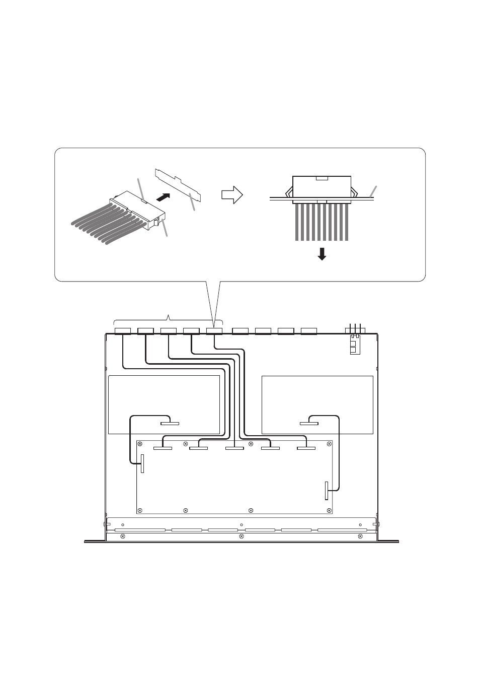
Step 6. Connect the FS-7000GM unit to its circuit board using the supplied connector-equipped cables.
Connect one end of the cable to CN301 on the FS-7000GM circuit board and insert the other cable
end into the rear panel-mounted connector receptacle opening for "GM ZONE CONT 1" (indicated on
the rear panel).
Similarly, connect the other cables to CN302 and "GM ZONE CONT 2," CN303 and "GM ZONE
CONT 3," CN304 and "GM ZONE CONT 4," and CN305 and "GM ZONE CONT 5."
Then, insert the cables affixed to the FS-7000GM's bottom surface with tape into CN101 and CN202
on the circuit board. The CN101 connects to CN4 on the circuit board already mounted in the FS-
7000GM unit, while the CN202 connects to CN9 (refer to the internal wiring diagram).
1
2
3
4
5
CN4
CN101
CN301
CN302
CN303
CN304
CN305
CN202
CN9
Note the connector's correct
insertion orientation.
Polarizing guide
Connector
Rear panel opening
(as viewed from the inside)
Insert the connector fully.
Rear panel
Toward internal circuit board
GM Zone Control terminals
FS-7000GM internal wiring diagram
Step 7. Replace the case after installation has been completed.
Note
Take care not to pinch cables when replacing the case.