Toa FS-7000 SERIES Installation User Manual
Page 27
27
9
10
11
12
13
14
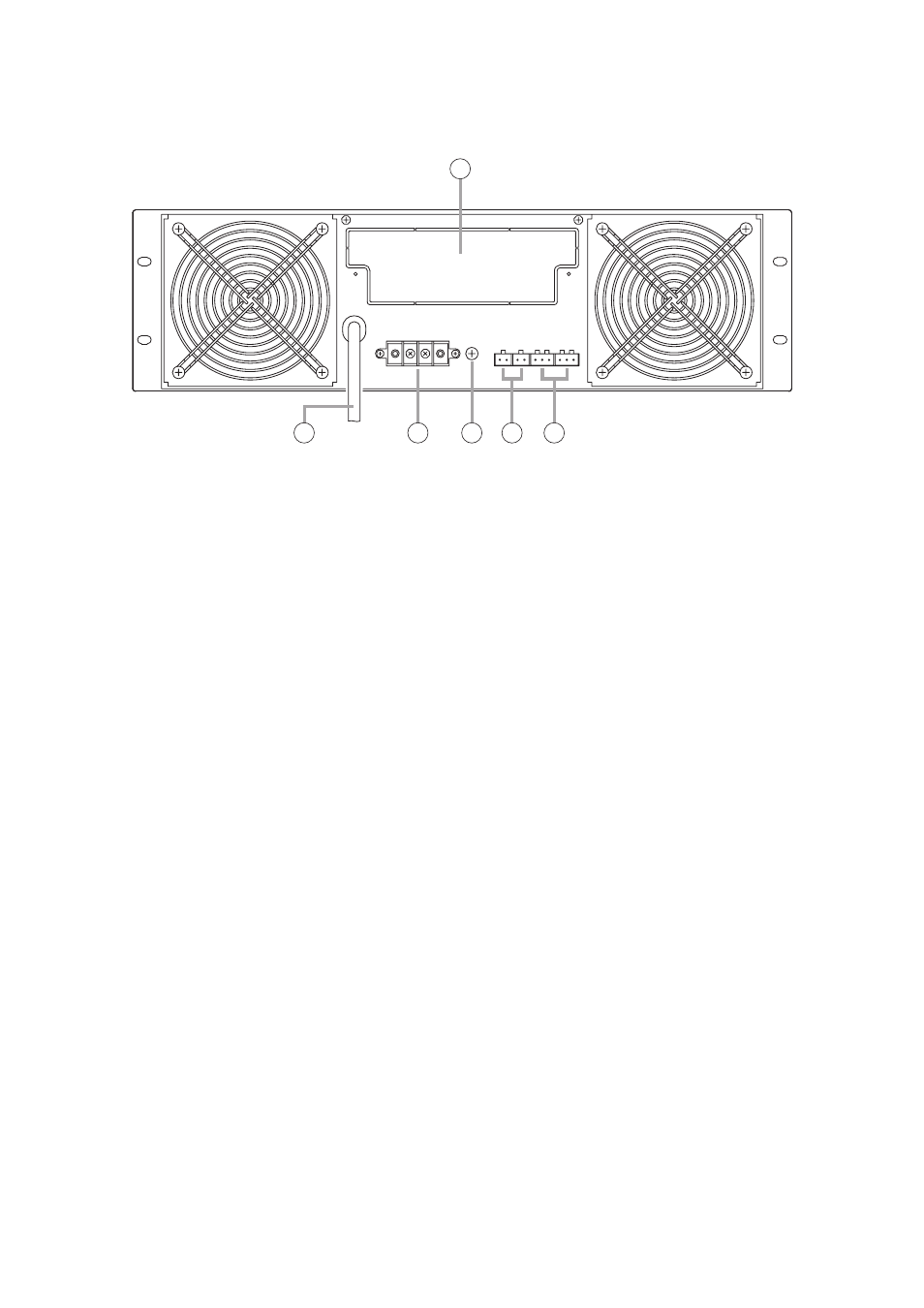
[Rear]
Figure shows the FS-7012PA.
9. YA-7000 Receptacle
Mount an optional YA-7000 module from this
receptacle. (See page 76.)
Note
Use of the YA-7000 permits the main amplifier to
be switched over to a standby amplifier if the
main amplifier fails.
10. Power Cord
Connect this cord to the wall AC outlet (230 V
AC, 50 Hz).
11. Speaker Output Terminal (with cover)
This high-impedance, 100 V line output is
connected to the FS-7000JP.
Note
Connect this terminal to the YA-7000 when the
YA-7000 has been mounted.
• FS-7006PA
M4 screw terminal; barrier distance: 9 mm; load
impedance: 16.7 Ω
• FS-7012PA
M4 screw terminal; barrier distance: 9 mm; load
impedance: 8.3 Ω
Note
Never connect this terminal to the speaker output
terminal of other FS-7006PA or FS-7012PA
power amplifier. Failure to follow this instruction
could lead to equipment failures.
12. Functional Earth Terminal
Connect this terminal to the functional earth
terminal of external equipment if excessive noise
is generated when the power amplifier is
connected to the external equipment. This could
reduce noise.
Note: This terminal is not for protective earth.
13. Volume Control Bypass Control Input Terminal
Bypasses Volume Control (3) on the front panel
and allows announcements to be made at
maximum volume.
(Open voltage: under 24 V DC; short-circuit
current: under 10 mA; 2P terminal block)
14. Audio Signal Input Terminal
Connect this terminal to the FS-7000CP's Priority
Output and BGM Output.
(0 dB, 10 kΩ, balanced, 3P terminal block)