Toa FS-7000 SERIES Installation User Manual
Page 13
13
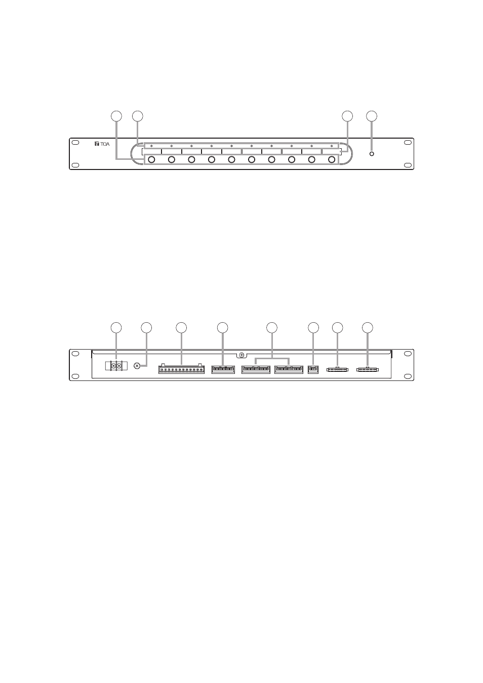
5.2. FS-7010CP Expansion Control Panel
The FS-7010CP is used to expand the broadcasting capacity of FS-7000 Series Voice Evacuation Systems.
Announcements and background music can be broadcast to up to 10 individual zones. Connecting the FS-
7000GM to the FS-7000CP/FS-7010CP combination permits broadcasts to be made to up to 20 zone groups.
[Front]
2
3
4
1
6
7
8
5
11
9
10
12
1. Power Indicator
Lights when power is supplied and the FS-
7010CP is ready for operation.
2. Zone Selector Keys
Press these keys to select broadcast zones. To
cancel the selection, press the keys again.
Multiple broadcast zones can be selected
simultaneously with the additional use of the FS-
7000GM.
3. Zone Indicators
Light to indicate current broadcast zones.
Note
These indicators also light during emergency
broadcasts when their corresponding zones are
selected by automatic fire alarm signals.
4. Broadcast Zone Fill-In Space
Write the names of zones to be selected with the
Zone Selector keys (2) in this space.
5. DC Power Input Terminal
Connect 24 V DC power to this terminal. Power is
supplied from the FS-7000PS.
(M3 screw terminal; barrier distance: 6.4 mm)
6. Functional Earth Terminal
Connect this terminal to the functional earth
terminal of external equipment if excessive noise
is generated when the external equipment is
connected to the FS-7010CP. This could reduce
noise.
Note: This terminal is not for protective earth.
7. Automatic Fire Alarm System Input Terminal
Connect this terminal to floor identifier signals
transmitted from the automatic fire alarm system.
The identifier signal designates broadcast zones
to provide audio alarm to such zones. (Open
voltage: 26 V DC; short-circuit current: under 5
mA; 12P terminal block; 10 zones + COM + COM)
Note: This terminal is not connected when the FS-
7000EV is not used.
8. RF Zone Control Terminal
Use this terminal to connect the FS-7000RF.
9. CP Control Terminal
Connect this terminal to the FS-7000CP or other
FS-7010CP units. All of the FS-7010CP units
within the system must be connected to the FS-
7000CP.
10. JP Control Terminal
Connect this terminal to the FS-7000JP Junction
Panel.
11. JP Zone Control Terminal
Connect this terminal to the FS-7000JP in order
to control speaker line ON/OFF operations.
12. GM Zone Control Terminal
Connect this terminal to the FS-7000GM when
the FS-7000GM is connected to the FS-7000CP.
[Rear]