Toa FS-7000 SERIES Installation User Manual
Page 33
33
6.3. 24 V DC Power Supply Expansion
If the addition of zones causes the total of current consumption of 24 V DC-operated equipment to exceed 5
A, then add the required number of the FS-7000PS panels.
[Notes]
• Make connections between negative (–) terminals of the 24VDC output of all FS-7000PS panels.
• Divide the power supply to 24 V DC-operated equipment in order to keep the current supplied from a single
FS-7000PS panel at 5A or less. (Refer to the following table showing each component's current
consumption at 24 V DC.)
Current Consumption
200 mA
150 mA
450 mA
200 mA
130 mA
Equipment
FS-7000CP
FS-7010CP
FS-7000JP
FS-7000AT
FS-7000EV
Current Consumption
110 mA
60 mA
90 mA
15 mA
Equipment
FS-7000GM
FS-7000RF
FS-7000RM
FS-7010RM
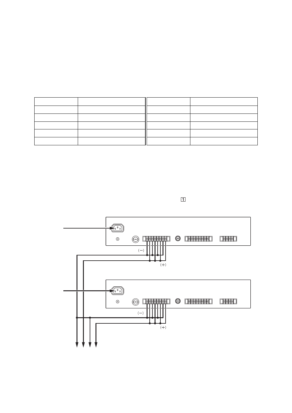
[Wiring Diagram]
The following figure shows only the wiring related to the expansion of the 24 V DC power supply.
230 V AC
FS-7000PS
230 V AC
FS-7000PS
DC POWER OUT
DC POWER OUT
To 24 V DC input of each DC-operated component
Cables used:
(See page 66; Table for Cables.)