Toa FS-7000 SERIES Installation User Manual
Page 50
50
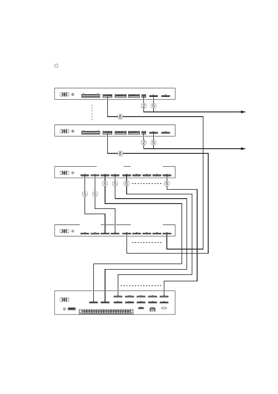
[Wiring Diagram (Example of 20 groups/100 individual zones)]
The figure below shows only the wiring related to group broadcasts. For the wiring of other models, refer to
the relevant system wiring diagrams, such as those for basic configuration and zone expansion.
FS-7000RF
2
1
2
1
4
5
3
2
1
2
1
2
1
4
5
3
2
1
2
1
4
5
3
FS-7000GM
(1st unit )
FS-7000GM
(2nd unit )
RF ZONE CONT
RF ZONE CONT
JP ZONE CONT
JP ZONE CONT
JP CONT
JP CONT
FS-7010CP
(6th unit *)
FS-7010CP
(10th unit *)
GM GROUP
CONT IN
GM GROUP
CONT IN
GM GROUP CONT
GM GROUP
CONT OUT
GM ZONE CONT
GM ZONE CONT
GM ZONE CONT
: Supplied cables
See page 64; Table for Cables.
To FS-7000JP that provides
Speaker lines 51 – 60
To FS-7000JP
that provides
Speaker lines 91 – 100
* If the FS-7000GM is connected to the FS-7000CP and 20 group selector keys are created, the 6th, 7th, 8th,
9th and 10th units of the FS-7010CP should be read as the 7th, 8th, 9th, 10th, and 11th units.