Speaker/attenuator connection diagram – Toa FS-7000 SERIES Installation User Manual
Page 53
53
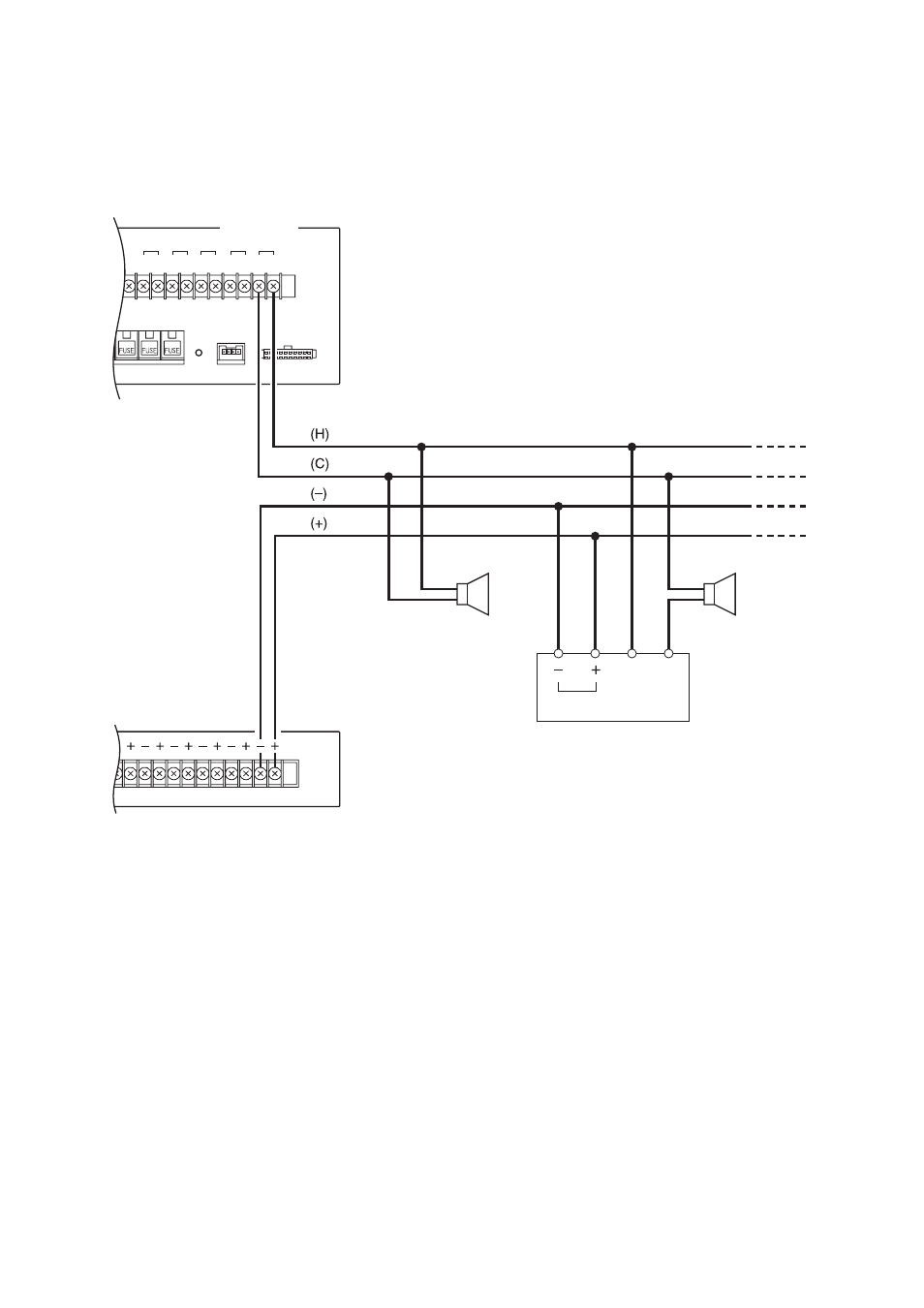
[Speaker/Attenuator Connection Diagram]
N
SP
COM
4-wire system attenuator
Bypassed when 24 V DC power is supplied.
Relay contact
FS-7000AT
FS-7000JP
H
C
1
H
C
2
1
2
H
C
3
H
C
4
H
C
5
3
4
5
6
SP OUT
ATTENUATOR CONT/
OUT
Note
The maximum output current of the FS-7000AT's ATT Control Output is 0.75 A per circuit. If the current
exceeds this limit, the FS-7000AT's built-in protection circuit cuts off the output. When a control current larger
than 0.75 A is needed, divide both the ATT Control Output lines and the FS-7000JP's speaker lines into 2 or
more lines.