Toa FS-7000 SERIES Installation User Manual
Page 40
40
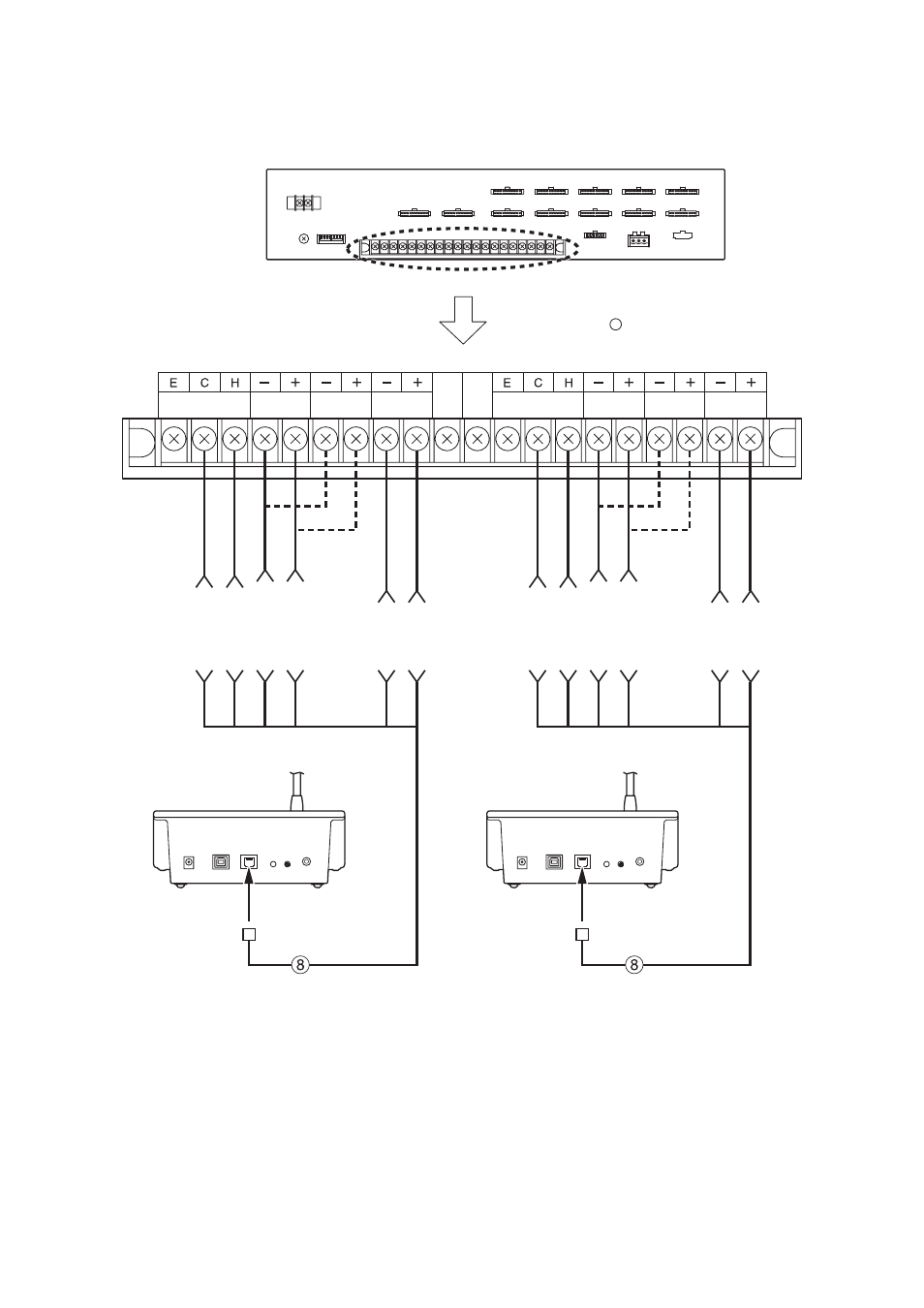
6.6.1. Connecting the FS-7000RF to 2 FS-7000RMs
: Supplied cable
See page 64; Table for Cables.
AUDIO
AUDIO
DC24 V #2
DC24 V #1 DC24 V #3
DC24 V #4 BUS #2/#4
BUS #1/#3
RJ45’s
Pin Arrangement
#5
AUDIO C
#5
AUDIO C
#4
AUDIO H
#4
AUDIO H
#8 DC 24 V –
#7 DC 24 V +
#8 DC 24 V –
#7 DC 24 V +
#6 BUS –
#3 BUS +
#6 BUS –
#3 BUS +
FS-7000RF
FS-7000RM
FS-7000RM
RF LINK
RF LINK
RJ45 connector
RJ45 connector
Connect the RJ45 connector to the FS-7000RM's FS-7000RF Link Terminal. Strip the other ends of the cable
and connect them to the FS-7000RF's FS-7000RM Link Terminal.
Notes
• If a long distance between the FS-7000RM and the FS-7000RF causes the FS-7000RM's voltage to drop
below 20 V, the power supply must be augmented using an AC adapter.
• The total cable length from the FS-7000RF to each FS-7000RM must not exceed 800 m.