Toa FS-7000 SERIES Installation User Manual
Page 63
63
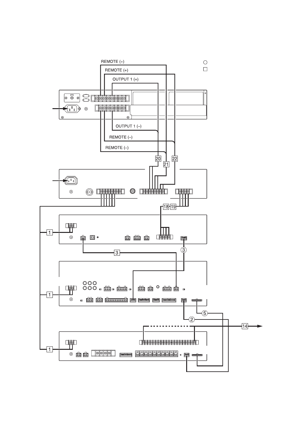
[Wiring Diagram]
The figure shows only the wiring related to the DS-029B Emergency Power Supply Panel.
For the wiring of other models, refer to the relevant system wiring diagrams, such as those for basic
configuration and zone expansion.
FS-7000PS
DS-029B
FS-7000EV
FS-7000CP
FS-7000JP
230 V AC
230 V AC
DC POWER OUT
EV OUT
DC POWER IN
IN
CONT
PS CONT
PS CONT
EV CONT
EV CONT
EV IN
START
EMERG POWER
DC POWER IN
DC POWER IN
JP CONT
JP ZONE /
GM GROUP CONT
SP OUT
JP CONT
JP ZONE CONT
Speaker lines
: Supplied cables
: Cables prepared separately
See page 64; Table for Cables.
Note
When not connecting the DS-029B Emergency Power Supply Panel, Cables No. 18 and No. 19 connecting
between both PS CONT terminals of the FS-7000PS and FS-7000EV are not needed.