Toa FS-7000 SERIES Installation User Manual
Page 15
15
6
7
8
5
11
9
10
12
13
14 15 16
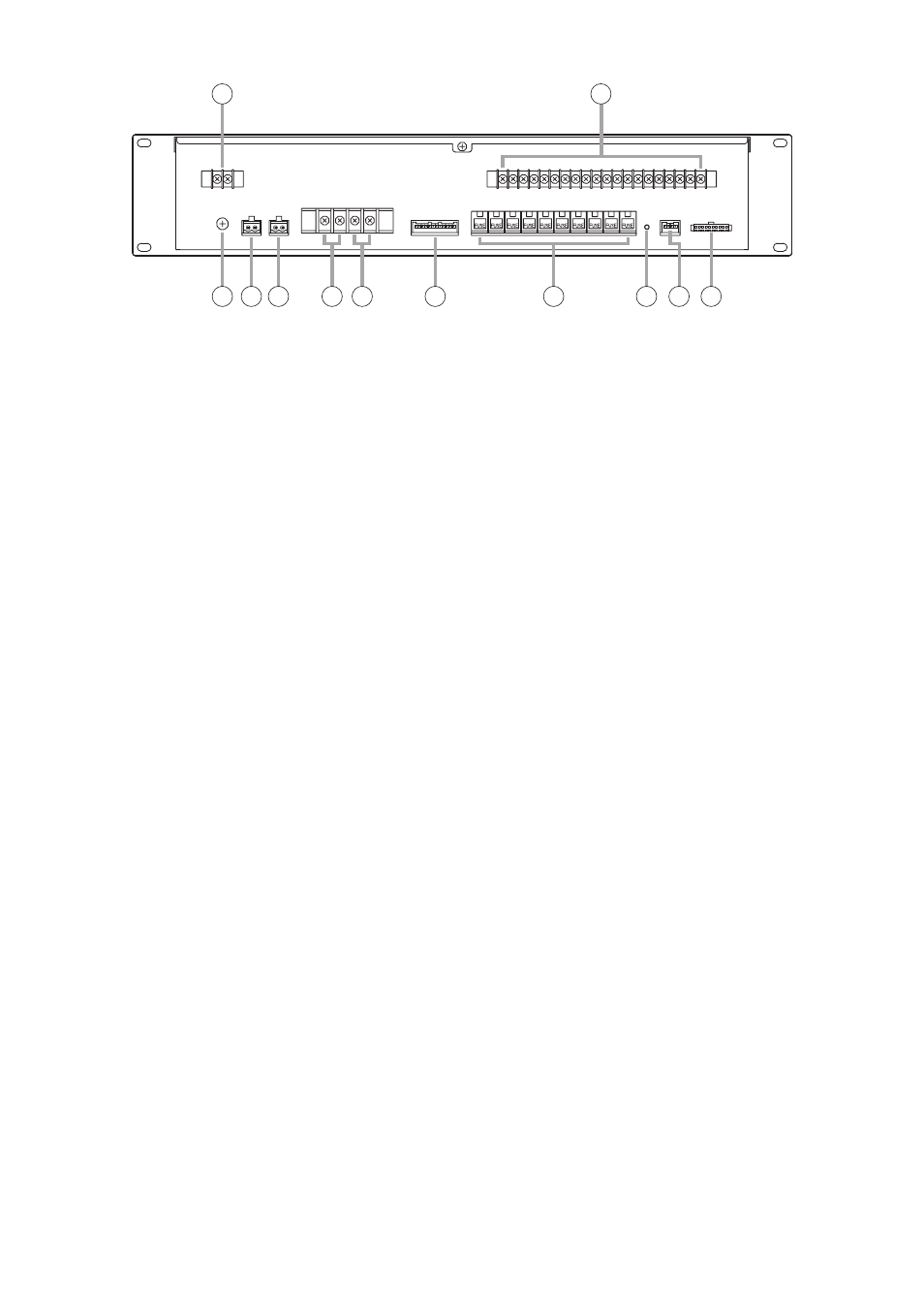
[Rear]
5. DC Power Input Terminal
Connect 24 V DC power to this terminal. Power
is supplied from the FS-7000PS.
(M3 screw terminal; barrier distance: 6.4 mm)
6. Speaker Output Terminal
Connect this terminal to speaker lines. Ten lines
can be connected.
Maximum per-line output (high impedance, 100
V line)
When the FS-7006PA amplifier is connected:
280 W
When the FS-7012PA amplifier is connected:
500 W
(M3 screw terminal; barrier distance: 6.4 mm)
7. Functional Earth Terminal
Connect this terminal to the functional earth
terminal of external equipment if excessive noise
is generated when the FS-7000JP panel is
connected to the external equipment. This could
reduce noise.
Note: This terminal is not for protective earth.
8. General Urgency/Emergency Mode Output
Terminal
Activated while a General urgency broadcast or
Emergency broadcast is being made.
(Open collector output; rated voltage: 30 V DC;
current capacity: 0.1 A; 2P terminal block)
9. Power Remote Output Terminal
Activated when a broadcast is made to any zone.
This terminal can be used for remotely
controlling the power amplifier's power supply.
(Relay output; rated voltage: 30 V DC; current
capacity: 1 A; 2P terminal block)
10. BGM Input Terminal
Connect this terminal to the power amplifier
intended for BGM broadcast.
(M4 screw terminal; barrier distance: 9 mm)
Note
Only 1 piece of FS-7006PA, FS-7012PA or YA-
7000 can be connected to this terminal. Never
connect 2 or more units to this terminal, as the
excessive load could cause the amplifier to fail.
11. Priority Input Terminal
Connect this terminal to the output of the power
amplifier intended for priority broadcast.
(M4 screw terminal; barrier distance: 9 mm)
Note
Only 1 piece of FS-7006PA, FS-7012PA or YA-
7000 can be connected to this terminal. Never
connect 2 or more units to this terminal, as the
excessive load could cause the amplifier to fail.
12. Attenuator Connection Terminal
Connect this terminal to the FS-7000AT.
13. Speaker Line Protection Fuses
Disconnect shorted speaker lines to prevent
adverse effects on other speaker lines.
Note
Install the fuse having the correct capacity for all
the connected speakers.
14. Reset Switch
Pressing this switch after removing the cause of
a speaker line short and replacing the blown
Speaker Line Protection Fuse (13) restores
broadcasts to that speaker line.
15. JP Control Terminal
Connect this terminal to the FS-7000CP and FS-
7010CP.
16. JP Zone Control Terminal
Connect this terminal to the FS-7000CP and FS-
7010CP to select speaker lines during priority
broadcasts.