B.2. arc system component parts, B.2.1. the arc system control console, B.2.2. application rate sensor – TeeJet ARC-6000 User Manual
Page 41: B.2.2.1. liquid application, Tandard, Ersion
B-3
98-05017
Rev.- 1
ARC 6000
CE & S
TANDARD
V
ERSION
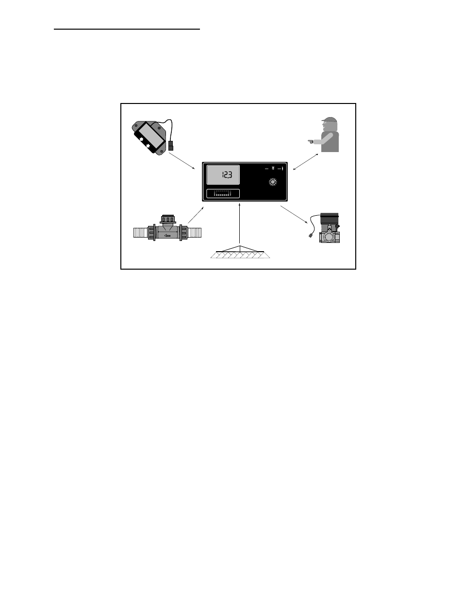
B.2. ARC SYSTEM COMPONENT PARTS
There are five major components in a complete ARC system, a console, ground speed sensor, flowmeter or pressure
sensor (Liquid), or rate sensor (dry), flow control valve, and boom interface. Each of these components is described
below so that the operator, will have a general understanding of how each of the parts performs its job.
Boom Width
Data
Ground Speed
Data
Application Rate
Data
Rate Change
Commands
Operator/Console
Input
Mid-T
Mid-Tec
ech
OFF
SET- UP
DEC.
ON
OPERATE
INC.
ARC-6000
Automatic
Rate Controller
MIDWEST TECHNOLOGIES, INC.
BOOMS
1 2 3 4 5 6 7 8 9
MID-TECH
MPH
DISPLAY SELECTOR
Speed
Field Area
Impl. Width
Distance
Test
Speed
Prime
Total Applied
Application Rate
Scan
Product Vol.
Total Area
% Rate
B.2.1. THE ARC SYSTEM CONTROL CONSOLE
The ARC control console is the heart of the system and actually performs three separate functions. The console is a
small computer with a sophisticated control program developed by MIDWEST TECHNOLOGIES. The console
continually monitors ground speed and active boom width. As these values change, the console immediately recalcu-
lates the required flow rate and makes necessary corrections.
The ARC control console performs the second function of allowing the operator to command the entire system “ON
THE GO” from the operator’s seat. The operator has complete control over the application rate. The rate can be altered
while the unit is applying.
The third function of the control console is to inform the operator about the status of the applicator. The control console
continually monitors the flow rate, vehicle ground speed and swath width. The ARC control console immediately
warns the operator if the system can no longer maintain accurate application. The warnings are both visual and audible,
to attract immediate attention. The large, backlighted LCD also displays instant readouts of application rate and volume
applied, vehicle ground speed, active boom width, distance traveled, and the area covered while applying.
B.2.2. APPLICATION RATE SENSOR
B.2.2.1. LIQUID APPLICATION
Some liquid ARC systems require a flowmeter in the main boom feed line to measure flow rate and to determine when
changes are needed in the position of the flow control valve. The flowmeter precisely measures the flow rate of the
liquid being discharged. The flowmeter is an impeller device. This means a specific volume of liquid flowing through
the flowmeter will rotate an impeller a specific number of revolutions. The ARC System is able to count the revolutions
of the impeller very accurately, allowing the console to calculate the exact flow rate of the liquid in the applicator
supply line.