Pressure sensor high/low calibration, Arc 6000 ce & s – TeeJet ARC-6000 User Manual
Page 14
98-05017
Rev.- 1
2-4
ARC 6000
CE & S
TANDARD
V
ERSION
Once the initial calibration number has been entered into the console, proceed to section 2.6.1.4 to fine tune the flowmeter
for maximum accuracy.
2.6.1.2. DETERMINING THE PRESSURE SENSOR INITIAL CALIBRATION NUMBER
The Pressure Sensor Calibration Number can be found by determining the "Gallons per Acre" rating for the type of nozzles
being used. First find the chart that represents the nozzle series you will use and the nozzle spacing of your boom. Then find
the nozzle size needed for the range of speeds and the rate needed. When the nozzle has been selected find the column of
nozzle ratings in "Gallons per Acre" at 10 MPH. Then, on the left of the chart, find the horizontal line representing the
ratings at 30 PSI. Where the column and row intersect you will find the "Gallons per Acre" rating of your nozzles at 10
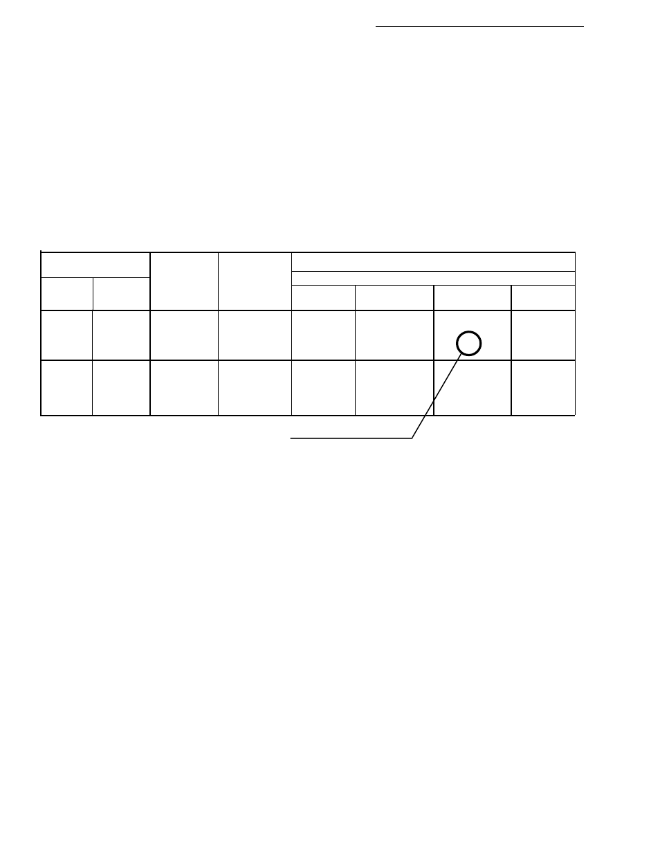
MPH and 30 PSI. This is the value to enter into the console as the pressure sensor Cal. #. For example, in the following chart,
for a floodjet K-SS10 nozzle, the row for 30 PSI and column for 10 MPH cross at 26.0 gallons per acre, the pressure sensor
cal. number for this particular nozzle.
NOTE: We recommend that these tests be done using water, and only after neutralizing the tank and system.
4
Gallons per Acre
Type
Floodjet
Tip No.
TK-SS10
TK-SS15
Liquid
Capacity
40" Spacing
Floodjet
Pressure
in
6
8
10
12
Nozzle
in PSI
GPM
MPH
MPH
MPH
MPH
10
1.0
25.0
16.6
14.9
12.4
K-SS10
20
1.4
35.0
26.0
21.0
17.5
30
1.7
43.0
32.0
26.0
21.0
40
2.0
50.0
37.0
30.0
25.0
10
1.5
37.0
28.0
22.0
18.6
K-SS15
20
2.1
53.0
39.0
32.0
26.0
30
2.6
64.0
48.0
39.0
32.0
40
3.0
74.0
56.0
45.0
37.0
Use this number as the cal. number in this example.
Use the following procedure to enter the flow sensor calibration number.
A. Set the console to the following positions;
Power
ON
Mode Selector
SET- UP
Master Switch
OFF
Display Selector
TOTAL APPLIED
B. Use the INC/DEC switch to select the desired flow sensor calibration number.
2.6.1.3. PRESSURE SENSOR HIGH/LOW CALIBRATION
The pressure sensor's low and high values must be set to match the readings from your pressure gauge following the proce-
dure below.
SETTING THE LOW SIDE:
A. Set the console to the following positions;
Power Switch
ON
Setup/Operate Switch
OPERATE
Display Selector Switch
PRIME
Master Switch
ON
At least one Boom Switch
ON (to release any trapped pressure)
(May have to remove nozzle if it has a check valve)
Ground speed
0 (zero)
GSO Switch
OFF