Carrier AQUAZONE RVC User Manual
Page 12
12
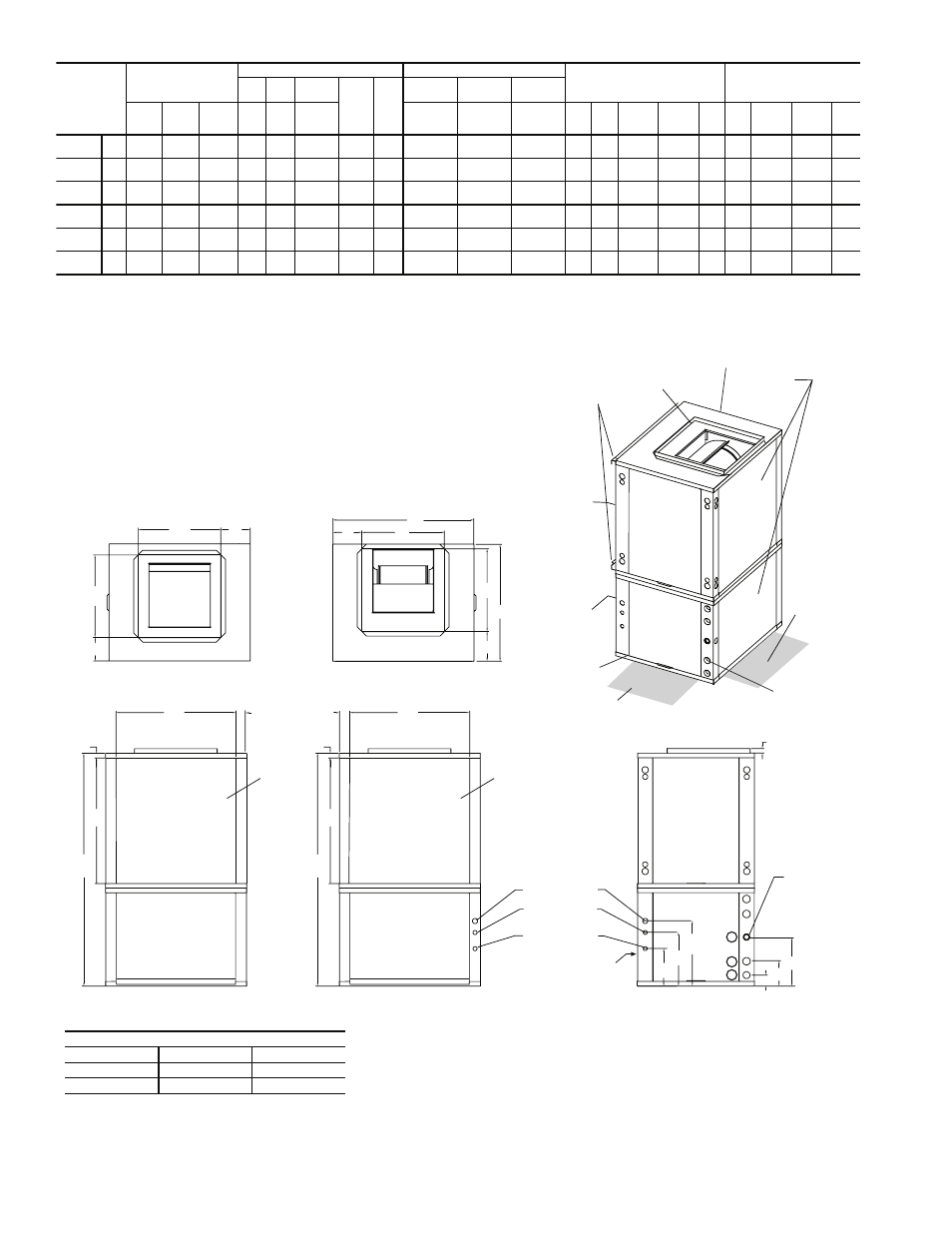
Fig. 7 — 50RVS Dimensional Data
NOTES:
1. Condensate is
3
/
4
-in. FPT and is switchable from side to front.
2. Vertical unit shipped with filter bracket only extending from unit 2.5 inches. This bracket should be removed when connecting return duct.
3. Discharge flange field installed.
4. Right and left orientation is determined by looking at water connection side.
50RVS
UNITS
OVERALL CABINET
WATER CONNECTIONS
ELECTRICAL KNOCKOUTS (in.)
DISCHARGE CONNECTION
Duct Flange Installed (
±0.10 in.)
RETURN CONNECTION
Using Air Coil Opening
1
2
3
Loop
Water
FPT
(in.)
HWG
FPT
(in.)
G
1
/
2
conduit
H
1
/
2
conduit
I
3
/
4
conduit
A
Width
B
Depth
C
Height
D
In
E
Out
F
Cond-
ensate
Therm
Ext Pump
Power
Supply
J
K
L
Supply
Height
M
Supply
Depth
N
O
P
Return
Depth
Q
Return
Height
R
015-018
in.
22.4
25.6
40.6
2.4
5.4
9.7
3
/
4
1
/
2
5.7
9.7
12.2
7.2
5.8
14.0
14.0
4.3
2.2
21.1
19.2
1.0
cm
56.8
65.1
103.1
6.1
13.7
24.6
14.5
24.6
31.0
18.3 14.7
35.6
35.6
10.9
5.6
53.6
48.8
2.5
024-030
in.
22.4
25.6
44.6
2.4
5.4
9.7
3
/
4
1
/
2
5.7
9.7
12.2
7.2
5.8
14.0
14.0
4.3
2.2
21.1
23.2
1.0
cm
56.8
65.1
113.3
6.1
13.7
24.6
14.5
24.6
31.0
18.3 14.7
35.6
35.6
10.9
5.6
53.6
58.9
2.5
036
in.
22.4
25.6
48.6
2.4
5.4
9.7
3
/
4
1
/
2
5.7
9.7
12.2
7.2
5.8
14.0
14.0
4.3
2.2
21.1
27.2
1.0
cm
56.8
65.1
123.4
6.1
13.7
24.6
14.5
24.6
31.0
18.3 14.7
35.6
35.6
10.9
5.6
53.6
69.1
2.5
042-048
in.
25.4
30.6
50.6
2.4
5.4
10.7
1
1
/
2
8.1
11.7
14.2
6.2
6.3
18.0
18.0
5.1
2.2
26.1
27.2
1.0
cm
64.5
77.8
128.5
6.1
13.7
27.2
20.6
29.7
36.1
15.7 16.0
45.7
45.7
13.0
5.6
66.3
69.1
2.5
060
in.
25.4
30.6
54.6
2.4
5.4
10.7
1
1
/
2
8.1
11.7
14.2
6.2
6.3
18.0
18.0
5.1
2.2
26.1
31.2
1.0
cm
64.5
77.8
138.7
6.1
13.7
27.2
20.6
29.7
36.1
15.7 16.0
45.7
45.7
13.0
5.6
66.3
79.2
2.5
070
in.
25.4
30.6
58.6
2.4
5.4
10.7
1
1
/
2
8.1
11.7
14.2
6.2
6.3
18.0
18.0
5.1
2.2
26.1
35.2
1.0
cm
64.5
77.8
148.8
6.1
13.7
27.2
20.6
29.7
36.1
15.7 16.0
45.7
45.7
13.0
5.6
66.3
89.4
2.5
AIRFLOW CONFIGURATION
Code
Return
Discharge
L
Left
Top
R
Right
Top
Access Panels
L Configuration - Top View-Left Return
R Configuration - Top View-Right Return
R
O
P
Isometric
View
L Configuration - Left Return Left View
- Air Coil Opening
Q
C
Condensate
3/4
“
FPT
Front View
H
1.000
G
F
E
D
I
Air Coil
Field Installed
Discharge Flange
(Shipped loose in
blower section)
Front
Back
R
O
P
Q
C
Back
Front
BSP
CAP
Standard Filter Bracket
ASP
ASP
Air Coil
Fr
o
n
t
M
K
L
N
F
ront
3’ Service
Access
Left Return
(right
Opposite)
K
B
M
A
L
J
3’ Service
Access
1
2
3
CSP
CAP
CSP
CSP
Air Coil
Air Coil Side
Air Coil Side
ASP
R Configuration - Right Return Right View
- Air Coil Opening
Front
Water Connection
1/2
“
Knockout
Power for
Condensate Pump
Low Voltage
1/2“ LV Knockout
Power Supply
3/4“ HV Knockout
Water
Connections
RIGHT RETURN
LEFT RETURN
LEGEND
ASP
— Alternate Service Panel
BSP
— Blower Service Panel
CAP — Control Access Panel
CSP
— Compressor Service Panel
a50-8169