Venting – Reznor BE Unit Installation Manual User Manual
Page 9
Form RZ-NA-I-FE/BE, Mfg P/N 98807, Rev 10, Page 8
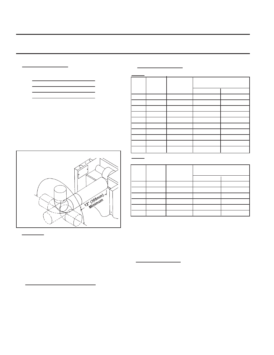
Venter Outlet Attachment Requirements:
•
If the pipe used in the vent run is larger than the diameter of the
venter outlet (See Vent Length Table 2), Make the transition at
the venter outlet.
•
A minimum of 12" (305mm) of straight pipe is required at the
venter outlet (or transition fitting) before installing an elbow in
the vent system. An elbow should never be attached directly to
the venter. An elbow attached to the straight pipe can be in any
position at or above horizontal. See Figure 8.
2. Vent Pipe
If installed with a horizontal vent run, use either vent pipe ap-
proved for a Category III heater or appropriately sealed 26-gauge
galvanized steel or equivalent single-wall pipe.
If at least half of the equivalent length of the vent system is verti-
cal, vent pipe approved for a Category I heater may be used.
Single-wall pipe or double-wall (Type B) vent pipe are suitable for
use with a Category I heater.
Use only one of the flue pipe diameters listed in the Vent Length
Tables for the furnace size being installed.
2A. Vent Pipe Diameter Reduction
If at least half of the equivalent length of the vent system is verti-
cal, the vent pipe diameter may be reduced one inch from the
standard diameter listed in Vent Length Table 1. Only single-wall
pipe is suitable for use when reducing the pipe diameter. A taper-
type reducer must be used. The maximum allowable vent length
remains the same. If required, double-wall pipe may be used at the
terminal end as shown in Figures 9 and 10. (Use the equivalent
length for elbows as shown in Vent Length Table 1 for the standard
vent pipe diameter. All elbows used in the vent system must be
considered.)
Figure 8 - Alternate Vent Directions (vent in any
position above horizontal;
minimum of 12" (305mm)
of straight pipe is
required before an
elbow)
3. Vent Length Tables
Table 1: Maximum Permissible Vent Lengths
Vent
Maximum
Equivalent Straight
Model
Pipe
Vent Length*
Length** - ft (M)
Diameter
ft (M)
90° Elbows
45°
Elbows
25
4"
30 ft (9.1 M)
3.5' (1 M)
1.8' (.5 M)
50
4"
40 ft (12.2 M)
5' (1.5 M)
2.5' (.8 M)
75
4"
50 ft (15.2 M)
7' (2.1 M)
3.5' (1.1 M)
100
4"
50 ft (15.2 M)
7' (2.1 M)
3.5' (1.1 M)
125
5"
50 ft (15.2 M)
5' (1.5 M)
.5' (.8 M)
165
5"
50 ft (15.2 M)
9' (2.7 M)
4.5' (1.4 M)
200
5"
50 ft (15.2 M)
8' (2.4 M)
4.0' (1.2 M)
250
5"
50 ft (15.2 M)
10' (3.0 M)
5' (1.5 M)
300
6"
50 ft (15.2 M)
11' (3.4 M)
5.5' (1.7 M)
400
6"
50 ft (15.2 M)
15' (4.6 M)
7.5' (2.3 M)
Table 2: Optional Maximum Permissible Vent Lengths
(Requires an increase in vent pipe diameter.)
Vent
Maximum
Equivalent Straight
Model
Pipe
Vent Length*
Length** - ft (M)
Diameter
ft (M)
90° Elbows
45° Elbows
100
5"
60 ft (18.3 M)
8' (2.4 M)
4.0' (1.2 M)
165
6"
60 ft (18.3 M)
10' (3.0 M)
5.0' (1.5 M)
200
6"
60 ft (18.3 M)
12' (3.7 M)
6.0' (1.8 M)
250
6"
70 ft (21.3 M)
8' (2.4 M)
4.0' (1.2 M)
300
7"
70 ft (21.3 M)
13' (4.0M)
6.5' (2.0 M)
400
7"
90 ft (27.4 M)
14' (4.3M)
7.0' (2.1M)
*Note 1: If the system contains all vertical pipe or a combination of
horizontal and vertical vent pipe, the Maximum Permissible Vent Length
shown in Tables 1 and 2 may be increased one foot for each foot vertical
rise up to a maximum increase of 10 feet for Model sizes 25 thru 100 and
up to 20 feet for Model sizes 125 thru 400.
**Reduce the maximum vent length by the amount indicated for each
elbow.
4. Vent System Joints
Vent system joints depend on the installation and the type of pipe being
used.
•
If using single wall, 26-gauge or heavier galvanized pipe, secure slip-fit
connections using sheet metal screws or rivets. Seal pipe joints either
with tape suitable for 550°F (such as Option FA1, P/N 98266) or high-
temperature silicone sealant.
•
If using Category III vent pipe, follow pipe manufacturer's instructions
for joining pipe sections. When attaching Category III pipe to the venter
outlet or the vent cap, make secure, sealed joints following a procedure
that best suits the style of Category III pipe being used.
•
If using double-wall (Type B) vent pipe (allowed only if 1/2 of the
equivalent vent length is vertical), follow pipe manufacturer's instruc-
tions for joining pipe sections. For joining double-wall pipe to the venter
outlet collar, single-wall pipe, and/or the vent cap, follow the instruc-
tions below.
10. Venting
These power-vented unit heaters are designed to operate safely and efficiently with either a horizontal or vertical vent. (Horizontal vent run is
recommended for maximum fuel savings.)
WARNING: Units installed in multiples require individual vent pipe runs and vent caps. Manifolding of
vent runs is not permitted due to possible recirculation of combustion products into the building and possible
back pressure effects on the combustion air proving switch.
Specific Venting Requirements
(read all before installing)
1. Venter (Flue) Outlet
Venter Outlet Size:
Model Size
Outlet Diameter
25-100
4"
125-250
5"
300-400
6"