Reznor BE Unit Installation Manual User Manual
Page 8
Form RZ-NA-I-FE/BE, Mfg P/N 98807 Rev 10, Page 7
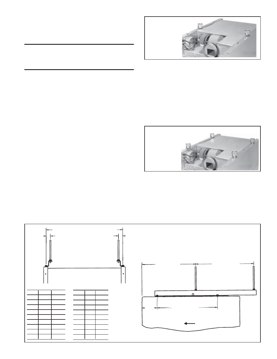
Figure 5 - Two-
Point Suspension
with Swivel
Connections
(fan models
only)
All blower models have legs that support the blower assembly dur-
ing shipping. After the unit is suspended, these legs should be re-
moved.
Be sure that the threaded hanger rods are locked to the heater as
shown in Figure 4.
WARNING: Unit must be level for proper
operation. Do not place or add additional weight
to the suspended heater. See Hazard Levels, page
2.
If an optional downturn air nozzle is used, the unit must be sus-
pended from four points to ensure level suspension. Two hanger
brackets are included in the downturn option package and must be
field-installed on fan-type units with standard two-point suspen-
sion. For additional information, refer to Paragraph 27 and the in-
structions that are furnished with the option package.
When blower-type units are equipped with an optional blower/
filter cabinet, there are two suspension points on the blower cabi-
net hanger bar. Suspend a unit equipped with a blower/filter cabinet
from four points, using the two heater hanger bracket assemblies
closest to the front of the heater and the two suspension points on
the blower/filter cabinet.
If one of the optional, field-installed hanger kits has been ordered for
your heater, it will have been shipped separately. Each option pack-
age includes a list of components and complete, step-by-step assem-
bly instructions.
Optional, Field-Installed Hanger Kits:
1) Four-Point Suspension (fan models only) - Option CK7
This option kit is designed to convert a fan-type heater from stan-
dard two-point suspension to four-point suspension. The kit con-
tains two additional hanger brackets.
2) Two-Point Swivel Connectors (fan models only) - Option
CK8 (See Figure 5)
The purpose of this option kit is to adapt the standard hanger bracket
so that the heater can be suspended from 1", threaded, stationary
pipe. The swivel connector screws "into" the threaded hanger bracket
on the heater and "onto" the 1" threaded pipe used for hanging the
heater. The kit includes two swivel hanger connector assemblies and
two lock washers.
Figure 7 - Suspension Dimensions for Model B Heater
with Hanger Kit Option CK19
A (Standard suspension points/hanger bars)
B (Suspension points with Option CK19)
1-3/8
(35)
1-3/8
(35)
Front View of Model B with Option CK19
Airflow
Side View of Model B with Option Ck19
17-3/8 (441)
18-3/4 (476)
19-15/32 (495)
4-7/8
(124)
3) Four-Point with Swivel Connectors (fan-models only) - Option
CK9 (See Figure 6)
This option package is designed to convert a fan-type heater from stan-
dard two-point suspension to four-point suspension with swivel con-
nectors. By installing this kit the standard fan-type heater can be hung
from four 1", threaded, stationary pipes. The kit includes two hanger
bracket assemblies, four swivel hanger connector assemblies and four
lock washers.
4) Four-Point Swivel Connectors - Option CK10 (See Figure 6)
This option package is used on a heater that is already equipped with
four-point suspension to adapt it for suspension from four 1", threaded,
stationary pipes. The kit includes four swivel hanger connector assem-
blies and four lock washers.
5) Special Four-Point Suspension with Nearly Equal Loading
(applies to blower models only) - Option CK19
(See Figure 7)
This suspension option is designed for special applications when a sus-
pension system is needed that has nearly equal loading at all four suspen-
sion points. Use this option in installations with spring isolation de-
signed for seismic protection or when threaded rod hangers are longer
than twelve inches.
Suspension points change with the addition of hanger kit Option CK19;
see Figure 7.
Figure 6 - Four-Point Suspension with Swivel
Connections (Applies to both
fan and blower models)
Dimensions (inches)
S i z e
A
B
25-50 11-7/8
9-1/8
75
13-7/8 11-1/8
100
15-7/8 13-1/8
125
21-5/8 18-7/8
165
18-5/8 15-7/8
200
21-5/8 18-7/8
250
27-1/8 24-3/8
300
27-1/8 24-3/8
400
35-3/8 32-5/8
Dimensions (mm)
S i z e
A
B
25-50
302
232
75
352
283
100
403
333
125
549
479
165
473
403
200
549
479
250
689
619
300
689
619
400
899
829