Gas piping and pressures, Venting (cont'd), Manifold or orifice pressure settings – Reznor BE Unit Installation Manual User Manual
Page 11
Form RZ-NA-I-FE/BE, Mfg P/N 98807, Rev 10, Page 10
11. Gas Piping and Pressures
WARNING
This appliance is equipped for a maximum gas
supply pressure of 1/2 pound, 8 ounces, or 14
inches water column. Supply pressure higher than
1/2 pound requires installation of an additional
service regulator external to the unit.
PRESSURE TESTING SUPPLY PIPING
Test Pressures Above 1/2 PSI: Disconnect the heater and
manual valve from the gas supply line which is to be tested.
Cap or plug the supply line.
Test Pressures Below 1/2 PSI: Before testing, close the manual
valve on the heater.
All piping must be in accordance with requirements outlined in the
National Fuel Gas Code ANSI/Z223.1a (latest edition) or CAN/CGA-
B149.1 and B149.2 (See Paragraph 1). Gas supply piping installation
should conform with good practice and with local codes.
Unit heaters for natural gas are orificed for operation with gas having a
heating value of 1000 (+ or - 50) BTUH per cubic ft. If the gas at the
installation does not meet this specification, consult the factory for
proper orificing.
Pipe joint compounds (pipe dope) shall be resistant to the action
of liquefied petroleum gas or any other chemical constituents of
the gas being supplied.
Install a ground joint union and manual shut-off valve upstream of the
unit control system, as shown in Figure 11. The 1/8" plugged tapping in
the shut-off valve provides connection for supply line pressure test
gauge. The National Fuel Gas Code requires the installation of a trap
with a minimum 3" drip leg. Local codes may require a minimum drip
leg longer than 3" (typically 6").
Gas connection sizes are included in the Dimensional Tables in Para-
graph 3. After all connections are made, disconnect the pilot supply at
the control valve and bleed the system of air. Reconnect the pilot line
and leak-test all connections by brushing on a soap solution.
Figure 11 - Supply
Piping Connection
WARNING: All components of a gas supply
system must be leak tested prior to placing
equipment in service. NEVER TEST FOR
LEAKS WITH AN OPEN FLAME. Failure to
comply could result in personal injury, property
damage or death.
Manifold or Orifice Pressure Settings
Measuring manifold gas pressure cannot be done until the heater is in
operation. It is included in the steps of the "Check-Test-Start" proce-
dure in Paragraph 25. The following warnings and instructions apply.
WARNING: Manifold gas pressure must never
exceed 3.5" w.c. for natural gas and 10" w.c. for
propane gas.
For Natural Gas: When the heater leaves the factory, the combination
gas valve is set so that the manifold gas pressure is regulated to 3.5" w.c.
Inlet supply pressure to the valve for natural gas must be a minimum of
5" w.c. or as noted on the rating plate and a maximum of 14" w.c.
For Propane Gas: When the heater leaves the factory, the combination
gas valve is set so that the manifold gas pressure is regulated to 10" w.c.
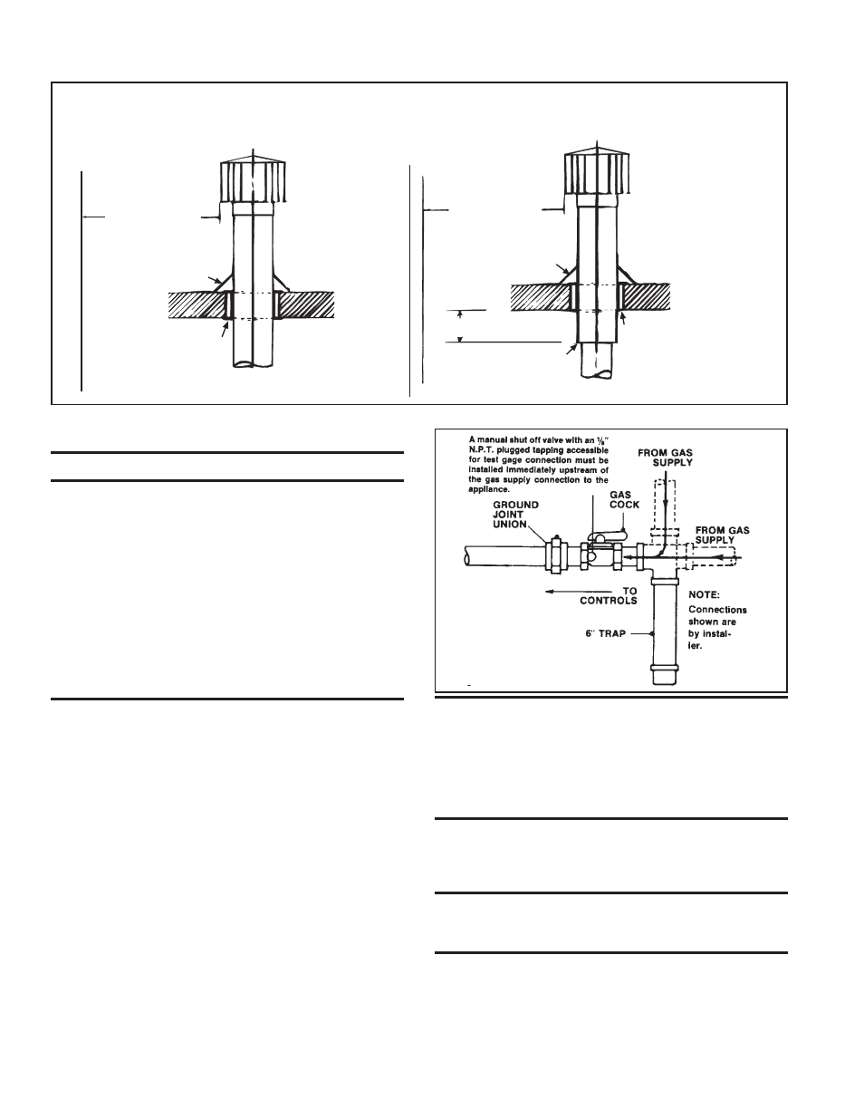
Figure 10 - Vertical Vent Terminals
10. Venting (cont'd)
6 (2M) minimum
6 (2M) minimum
Approved clearance thimble
for single-wall vent pipe is
required when flue pipe
extends through
combustible materials.
Parapet or Adjoining Building
Vertical flue extension to
be 6 (152mm) higher than
anticipated snow depth but
no less than 2 feet (610mm)
above the roof.
Vertical pipe extension
must be insulated.
Roof Flashing
Roof - pitched
from 0 to 45°
Vertical flue extension
to be 6 (152mm) higher
than anticipated snow
depth but no less than
2 feet (610mm) above the
roof.
6 (152mm) minimum
Roof Flashing
Roof - pitched
from 0 to 45°
Approved clearance thimble is
required when flue pipe extends
through combustible materials.
Follow the requirements of the
double-wall pipe manufacturer.
Follow instructions on page 9
to join single and double-wall
pipe and to seal the connection.
Parapet or Adjoining Building
Single-Wall Vent Run and Single-Wall Terminal End
Single-Wall Vent Run and Double-Wall Terminal End