Pilot and ignition system, Flash carryover, Burner orifices – Reznor BE Unit Installation Manual User Manual
Page 26: Heat exchanger, Fan or blower
Form RZ-NA-I-FE/BE, Mfg P/N 98807 Rev 10, Page 25
Orifice
Compression
Fitting
Pilot
Tubing
Flame Rod
Figure 33 - Pilot
Burner Spark Gap
CAUTION: Due to high voltage on pilot spark wire
and pilot electrode, do not touch when energized.
See Hazard Levels, page 2.
Figure 34 -
Pilot
Assembly
Figure 32 - Pilot Removal
Pilot Hole
Cover Plate
.100
spark
gap
10. To replace the burner rack assembly and the bottom panel,
reverse the above procedure (Steps 1-8).
Individual burners may be cleaned using air pressure. Use an air nozzle
to blow out scale and dust accumulation from the burner ports. Alter-
nately, blow through burner ports and venturi.
CAUTION: Eye protection is recommended.
Use a fine wire to dislodge any stubborn particles. Do not use anything
that might change the port size.
When any service is completed, be careful to reassemble correctly to
ensure that no unsafe conditions are created. When re-lighting, always
follow the lighting instructions on the heater.
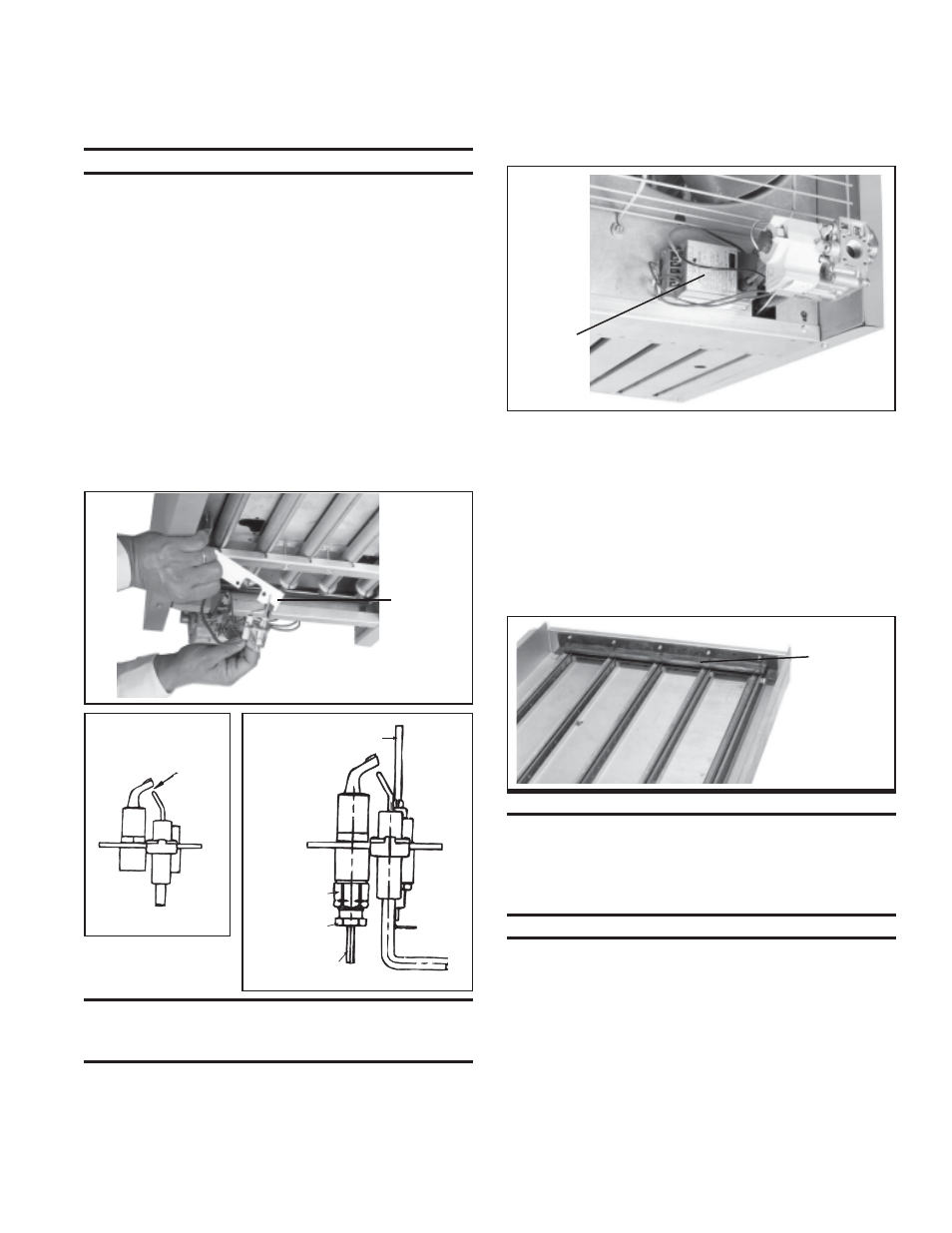
34. Pilot and Ignition System
The pilot can be serviced by opening the bottom access panel of the
heater. Follow the first four steps of instructions for Burner Rack
Removal, Paragraph 33. The pilot can be removed to check the wiring,
the spark gap, or to remove the orifice for cleaning. When the pilot is re-
installed, be sure to include the pilot hole cover plate.
Spark gap must be maintained to .100". (See Figure 33.)
In the event the pilot flame is short and/or yellow, check the pilot
orifice for blockage caused by lint or dust accumulation.
Remove the pilot orifice and clean with air pressure. Check and clean
the aeration slot in the pilot burner.
The ignition controller of the intermittent electronic ignition pilot
system is visibly located on the back of the heater. (See Figure 35.) Do
not attempt to disassemble the ignition controller. There are no field
replaceable components in the control enclosure. However, each heat-
ing season the lead wires should be checked for insulation deterioration
and good connections.
Proper operation of the electronic spark ignition system requires
a minimum flame signal of .2 microamps as measured by a
microampmeter.
For further information and check out procedure on the intermittent
electronic ignition pilot system, refer to the manufacturer's control
operating instructions supplied with the heater.
Figure 35
- Ignition
Controller
Location
Ignition
Controller
for Spark
Pilot
Figure 36 -
Burner
Rack Flash
Carryover
Flash
Carryover
36. Flash Carryover
See Figure 36. The burner carryover system receives its gas supply
from the main burner ports. Check the carryover assembly and also the
main burner ports for cleanliness. Clean with air pressure.
35. Burner Orifices
Heaters are shipped with orifices of proper size and type for gas and
altitude specified on the order. When ordering replacement orifices,
give BTUH content, specific gravity of gas, and altitude, as well as
model and serial number of the heater.
CAUTION: Eye protection is recommended.
37. Heat Exchanger
The outside of the heat exchanger can be cleaned from the front of the
heater with an air hose and/or a brush. Remove all accumulated dust and
grease deposits.
CAUTION: Eye protection is recommended.
The inner surfaces of the heat exchanger can be reached for cleaning
with the burner rack removed. (See Paragraph 33.) Cleaning can be done
with a long furnace brush or a heavy wire to which steel wool has been
attached. Brush up and down inside each heat exchanger tube until all
foreign material is removed. A flashlight is helpful in examining the
upper section of the tube.
38. Fan or Blower
Remove dirt and grease from the motor.
On fan model units, remove dirt and grease from the fan guard and
blades. Use care when cleaning the fan blades to prevent causing mis-
alignment or imbalance. Check that the hub of the fan blades is secure to
the shaft.