Burner rack removal, Service and maintenance (cont'd) – Reznor BE Unit Installation Manual User Manual
Page 25
Form RZ-NA-I-FE/BE, Mfg P/N 98807, Rev 10, Page 24
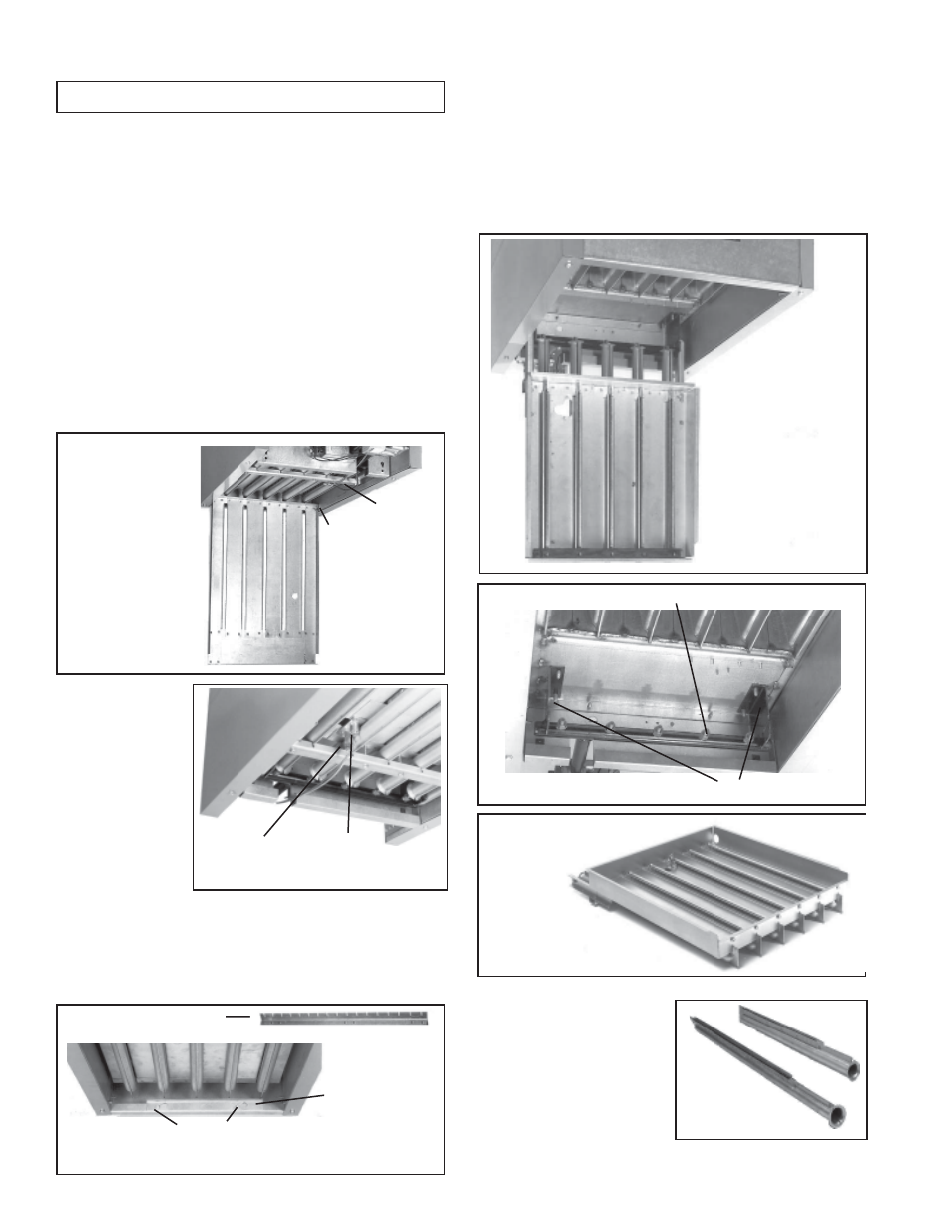
Figure 31 -
Individual
Burners
Figure 30 -
Burner Rack
Completely
Removed
Burner Assembly Support Brackets
Figure 29
Burner Orifices
Figure 25 -
Bottom
Access
Panel Open
Push
hinge
pin to
remove
bottom
panel
Pilot
Location
Figure 28 -
Burner Rack
Hinged Down
Pilot
Tubing
Flame
Sensor Lead
Figure 26 - Spark Pilot Location
Burner Rack Support
with Indexing
Figure 27 - Burner Rack Support
and Retaining Screws
Burner Rack
Support on units
manufactured
prior to 8/91 was
not indexed
Screws
33. Burner Rack Removal
These unit heaters have a convenient bottom access panel. The pilot is
attainable with the bottom panel open. With the access panel removed,
the burner rack assembly will hinge down for removal. Use the follow-
ing step-by-step instructions for removal of the bottom access panel
and the complete burner rack assembly.
Instructions for Burner Rack Removal (See
Figures 25-28.)
1. Shut the gas supply off ahead of the combination valve.
2. Turn off electric supply.
3. Remove the two sheet metal screws located at the rear of the bottom
panel.
4. Allow bottom panel to hinge down from the front.
5. Push in one of the two spring-loaded hinge pins located at the front
of the bottom panel (inside), and completely remove the bottom
panel.
NOTE: Use only factory-authorized replacement parts.
SERVICE AND MAINTENANCE (cont'd)
6. The bottom of the
pilot is now vis-
ible. Do the fol-
lowing:
(a) Disconnect the pi-
lot tubing from the pi-
lot burner.
(b) Disconnect the
flame sensing wire
and high tension
(spark) lead from the
ignition controller.
7A. Heaters manufactured beginning 8/91 (Serial No. Date Code
AQH) - The burner rack is indexed as illustrated in Figure 27. While
supporting the burner rack, remove the screws (two or three) that
hold the burner rack support. (For screw location, refer to Figure
27.) Remove the burner rack support allowing the burner rack as-
sembly to swing down (See Figure 28).
7B. Heaters manufactured prior to 8/91 (Serial No. Date Code AQH)
Loosen the sheet metal screws (two or three) located at the front of
the burner rack assembly. See Figures 27. These screws retain the
burner rack support. While supporting the burner rack assembly,
slide the burner rack support and remove it from the screws, allow-
ing the burner rack assembly to swing down (See Figure 28).
8. To Remove the Burner Rack -- With the burner rack assembly
"hanging" down, lift up on the rear and slide the assembly up and
out of the manifold support brackets.
9. To remove the individual burners:
a. Remove the flash carryover
(one screw per burner).
b. With the burner rack upside
down, remove the sheet metal
screws (located at the rear) that
retain the burner holddown.
c. Lift the rear of the burner up-
ward slightly and pull back, re-
moving the individual burners.
d. To replace individual burners, reverse the above procedure.