Electrical supply and connections, Thermostat and thermostat connections – Reznor BE Unit Installation Manual User Manual
Page 13
Form RZ-NA-I-FE/BE, Mfg P/N 98807, Rev 10, Page 12
12. Electrical Supply and Connections
All electrical wiring and connections, including electrical grounding
MUST be made in accordance with the National Electric Code ANSI/
NFPA No. 70 (latest edition) or, in Canada, the Canadian Electrical
Code, Part I-C.S.A. Standard C22.1. In addition, the installer should be
aware of any local ordinances or gas company requirements that might
apply.
Check the rating plate on the heater for the supply voltage and current
requirements. A separate line voltage supply with fused disconnect
switch should be run directly from the main electrical panel to the
heater. All external wiring must be within approved conduit and have a
minimum temperature rise of 60°C. Conduit from the disconnect switch
must be run so as not to interfere with the service panels of the heater.
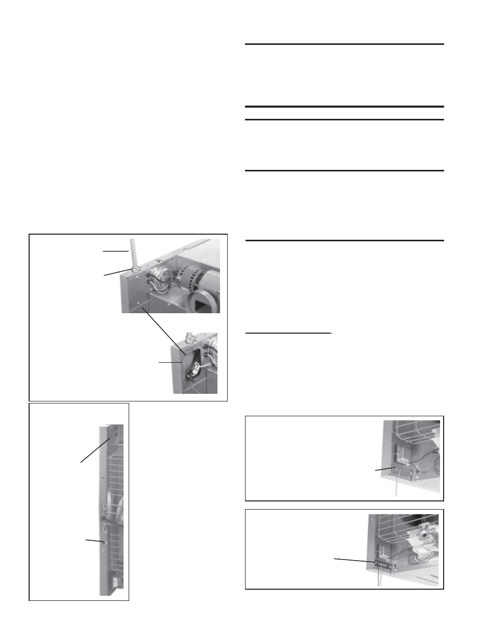
The electrical supply connects at the top back of the heater in the left
corner (left when facing the back of the heater). A threaded hole is
provided for a standard 1/2" electrical fitting.
The wiring access panel is easily removed for field connections. Con-
sult the wiring diagram supplied with your heater. Replace the panel
after the wiring connections are made.
If the heater has field-installed options that require electrical connec-
tions, consult the instruction sheet and wiring diagram supplied in the
option package.
Figure 12 - Electrical
Connections
Remove
Access
Panel to
make
connections
with the appliance must be replaced, it must be
replaced with wiring material having a temperature
rating of at least 105°C, except for limit control
and sensor lead wires which must be 150°C. See
Hazard Levels, page 2.
13. Thermostat and Thermostat
Connections
A thermostat is not standard equipment but is an installation require-
ment. Use either an optional thermostat available with the heater or a
field-supplied thermostat. Install according to the thermostat
manufacturer's instructions. Make sure that the heat anticipator setting
on the thermostat is in accordance with the amperage value noted on
the wiring diagram of your heater.
Terminal Strip Connections - The standard heater is equipped with
a two-screw terminal connector strip (See Figure 14) for easy connec-
tion to the low voltage controls (24V). When factory-installed options
require two-stage thermostat control, the heater is equipped with a SP-
ST relay and a four-screw terminal connector strip (See Figure 15).
If your heater requires field installation of the four-screw terminal strip
and the relay, follow the instructions packaged with the relay or ther-
mostat option.
If equipped with
unit-mounted
disconnect
switch, on/off
toggle switch is
near access
panel to
electrical
supply junction
box.
Circuit breaker
button for
Option AI-1
unit-mounted
disconnect
switch
Threaded Hole for
Standard 1/2"
Fitting
Figure 13 - Optional Unit-
Mounted Disconnect
Field Wiring from
Disconnect in
Conduit
Note: Fan-type heaters
with optional built-in
disconnect switch, have
an on/off switch located
near the electrical
supply access panel.
WARNINGS: On a heater with a unit disconnect
switch (Option AI-1), if the power is turned off at
the switch, the supply lead in the electrical supply
junction box (Figure 12) remains energized. If
service is to be done in the supply junction box,
turn off the power at the remote disconnect switch.
If you turn off the power supply, turn off the gas.
The operating sequence of the heater can be found on the heater wiring
diagram and is published in Paragraph 25, Check Installation and Start-
Up. Typical wiring diagrams are on the next four pages, showing
standard single-stage heating with spark pilot with and without lock-
out.
CAUTION: If any of the original wire as supplied
A fan-type heater may be
equipped with a built-in fused
disconnect switch (Option AI-
1). If the heater is equipped with
a built-in disconnect switch, a
two-position toggle (on/off)
switch is located near the elec-
trical supply access panel (See
Figures 12 and 13).
This switch may be used to dis-
connect the power when servic-
ing the heater other than in the
supply junction box.
Specific wiring diagrams that in-
clude standard and factory-in-
stalled options are included with
the heater. Check the wiring dia-
gram to identify optional equip-
ment.
Figure 14 -
Two Screw
Terminal Connector Strip
Figure 15 -
Four Screw
Terminal Connector Strip
(Paragraph 13 continued on page 17.)
Two Screw Terminal
Connector Strip for 24-
volt Wiring
Four Screw Terminal
Connector Strip for
24-Volt Wiring