Mounting furnaces (indoor), Mounting outdoor models, Suspending furnaces – Reznor XE Unit Installation Manual User Manual
Page 9: Mounting furnaces (indoor) mounting outdoor models, 7b. mounting outdoor model series crgb and rpb, Curb cap base, Mounting indoor furnaces
Form I-XE/CRGB/RPB, Page 8
Curb Cap Base
Outdoor systems are equipped with a load bearing curb cap which
forms an integral part of the unit. This curb cap has welded joints and
has a "skirt" which fits over a roof curb to provide a weatherproof
installation. Four holes are provided at the curb cap corners for lifting
the unit. These holes do not interfere with unit weatherproofing. The
curb cap is not designed to be placed directly on the roof surface.
The system may be mounted on an optional roof curb purchased with
the unit, a field-supplied roof curb, or field-supplied supports. If the
system has a downturn plenum and/or a bottom return air opening, a
roof curb is recommended to provide a weatherproof installation as well
as more workable clearances for ductwork. If the unit has an optional
cooling coil cabinet, the cabinet is shipped separately and attached in
the field. The cooling coil cabinet has a curb cap base that "matches and
extends" the length of the system base.
Mounting on Field-Supplied Supports (without a roof curb) - Prior
to installation, be sure that the method of support is in agreement with
all local building codes and is suited to the climate. If considering this
type of installation in snow areas, it is recommended that the 4x4 wooden
rails underneath the system be on cross-support structure at least 12"
higher than the roof surface (see support locations in FIGURE 6B).
Whether the supports are being mounted directly on the roof or being
placed "up" on additional structure, the horizontal length of the system
should be supported by two 4x4 treated wooden rails. Cut the rails to
the appropriate length (Dimension "A") in FIGURE 6A. (NOTE: Al-
though dimensions are included for units with a downturn plenum cabi-
net, it is strongly recommended that a full roof curb be used on an
installation with a downturn plenum cabinet and/or a bottom return air
duct.)
Space the 4x4 wooden rails (See "B" Dimension, FIGURE 6A) so that
the curb cap "skirt" will fit over the edge of the boards with the rails
setting inside the horizontal length of the curb cap.
If the rails are being laid directly on the roof, position them as shown in
FIGURE 6A. Set the system on the rails, leaving the "ends" underneath
open for ventilation.
WARNING: Unit must be level for proper
operation. Do not place or add additional weight to
a suspended unit. See Hazard Levels, page 2.
Suspending Furnaces
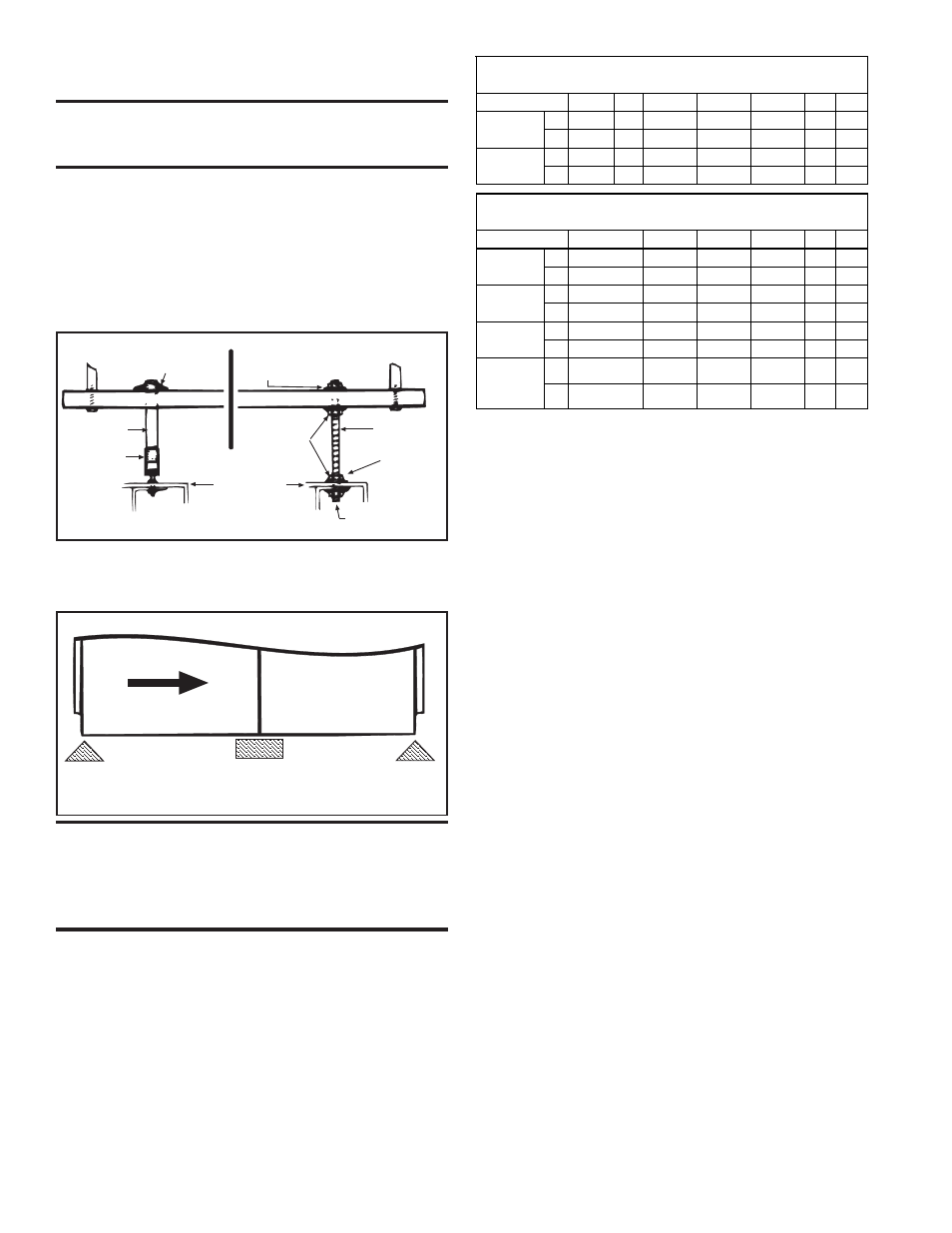
These indoor, packaged furnace/blower systems have four-point sus-
pension. See hanger dimensions in Paragraph 4, FIGURE 1A. At each
suspension point, the unit is factory-equipped with a free-turning, fe-
male, 1" (NPT) pipe hanger. Suspend by connecting the pipe hanger to
a 1" threaded pipe. See the suspension method on the left in FIGURE 4.
As an alternative method, the factory-installed pipe hanger may be
removed and the heater suspended as illustrated on the right in FIG-
URE 4.
Standard Assembly
Installer Replaced Assembly
1 Pipe Flange
Washer Nut Assembly
1 Pipe
Threaded
Socket
Washer Nut
Assembly
3/8 Rod
(Standard
Assembly
Removed)
Access through
the side panel
Heater Top
FIGURE 5 - Support Locations for Indoor Systems
7B. Mounting Outdoor Model Series CRGB
and RPB
Rigging - Lifting holes are provided for rigging. Use spreader bars when
lifting to prevent chains or cables from damaging the unit. If the unit is
being mounted on a roof curb, apply caulking to the roof curb prior to
lifting the unit to the roof and setting it on the curb. See FIGURE 8, page
10.
If the system includes an outside air hood and/or a shipped-separate
cooling coil cabinet, attach them after the unit is in place.
If the system includes a cooling coil cabinet, the cooling coil cabinet
must be lifted to the roof separately, set on the roof curb or supports,
and attached to the furnace.
WARNING: Do not support an indoor/gravity-
vented system with four corner support legs. The
system requires horizontal support at cabinet joint
as illustrated in FIGURE 5. Bottom clearance to
combustibles must be observed.
7A. Suspending/Mounting Indoor, Gravity-
Vented Models XE/HXE (cont'd)
Location - When selecting a location for an outdoor installation, posi-
tion the unit so that the air inlet will not be facing into the prevailing
wind.
When the unit is mounted on a roof over 20 ft (6 M) high, has parapet
walls or obstructions within 30 ft (9.1M), or is subject to winds over 25
mph, installation of a power-vented unit (Model Series RPB) is recom-
mended.
Blower Section
Furnace
Section
Airflow
Support the unit at each end and where the blower cabinet and
furnace section join. Support at cabinet joint must extend
horizontally supporting both sections.
FIGURE 4 - Suspension Methods
Mounting Indoor Furnaces
Indoor packaged systems require six support locations. See FIGURE 5.
All supports must be non-combustible.
Size
75, 100 125 150, 175 200, 225 250, 300 350 400
CRGB
lbs
439
472
510
529
573
624
655
Series
kg
199
214
231
240
260
283
297
RPB
lbs
-- 482
520
534
588
630
662
Series
kg
--
219
236
242
267
286
300
Approximate Net Weight (lbs/kg) - Optional Cooling Coil Cabinet
Size
150, 175 200, 225 250, 300 350 400
DX
lbs
464
551
661
753
848
kg
269
250
300
342
385
DX with
lbs
593
689
813
914 1018
Downturn kg
269
313
369
415
462
Chilled
lbs
457
544
654
746
841
Water
kg
207
247
297
338
381
lbs
586
682
806
907 1011
kg
266
309
366
411
459
Approximate Net Weight (lbs/kg) - Outdoor Systems
(blower and furnace sections only)
75, 100, 125
377
167
490
222
(includes approximate weight of a coil with 12fpi)
171
497
225
369
Chilled
Water with
Downturn