Dimensional data, Dimensions – Reznor XE Unit Installation Manual User Manual
Page 4
Form I-XE/CRGB/RPB, P/N 131782 Rev 5, Page 3
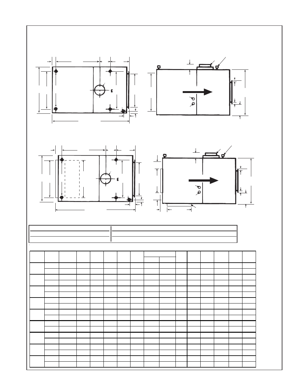
4. Dimensions
FIGURE 1A - Dimensions (inches and mm) of Indoor/Gravity Vented System
3/4 (19)
J
G
F
B
W C X
K
A
59 (1499)
4 (102)
2-1/8
(54)
Blower
Furnace
Gas
Top View
Side View
AIRFLOW
Control Wiring
Entrance
Supply Wiring
Entrance
Furnace
Blower
E
18
(457)
3/4 (19)
H
K
3-5/8 (92)
8 (203)
3/4
(19)
(4)Mounting Sockets
1 IPS free turning
female pipe thread
1-3/4 (44)
J
G
F
B
W C
X
K
A
60 (1524)
4 (102)
2-1/8
(54)
Blower
Furnace
Gas
Top View
Side View
AIRFLOW
Control Wiring
Entrance
Supply Wiring
Entrance
Furnace
Blower
19-1/2
(495)
18
(457)
3/4 (19)
H
K
3-5/8 (92)
8 (203)
3/4
(19)
(4)Mounting Sockets
1 IPS free turning
female pipe thread
C
3-1/4 (83)
D
19-1/2
(495)
3-1/4 (83)
Vertical return air
opening is capped
at the factory.
Dimensions of Model (H)XE with Standard Blower Cabinet (Standard blower cabinet has "full open" end and will not accommo-
date dampers. An optional cabinet is available with a smaller horizontal inlet that will accommodate dampers; see dimensional
drawing below. An optional bottom inlet will also accommodate dampers.)
Dimensions of Model (H)XE with Optional Blower Cabinet (Optional blower cabinet has a horizontal inlet that will accommodate
dampers. The cabinet also has a bottom inlet that is shipped with a cap; the bottom inlet will accommodate dampers.)
Dimension Key:
A x 18" (457mm) = Discharge Opening
B = Hanger Centerline - Furnace Section
C x E = Return Air Opening with Standard Cabinet
C x 19-1/2" (495mm) = Return Air Openings with Optional Cabinet
X = Hanger Centerline - Standard and Optional Blower Cabinet
Dimensions (inches and mm) - Gravity-Vented/Indoor Models XE/HXE
Gas Connection
Natural Propane
inche s
12-1/2
13-1/2 17-3/8 9-1/2 27-3/4
18
1/2
1/2
3-3/4 32-1/4 36-1/2
5 Rd
22
16-1/4
mm
318
343
441
241
705
457
13
13
95
819
927
127 Rd
559
413
inche s
12-1/2
13-1/2 17-3/8 9-1/2 27-3/4
18
1/2
1/2
3-3/4 32-1/4 36-1/2
6 Rd
22
16-1/4
mm
318
343
441
241
705
457
13
13
95
819
927
152 Rd
559
413
inche s
15-1/4
16-1/4 17-3/8 9-1/2 27-3/4
18
1/2
1/2
3-3/4 32-1/4 36-1/2
7 Ov
22
16-1/4
mm
387
413
441
241
705
457
13
13
95
819
927
178 Ov
559
413
inche s
20-3/4
21-3/4
23
9-1/2 27-3/4 19-3/8
1/2
1/2
2-3/8 32-1/4 36-1/2
8 Ov
27-1/2 21-3/4
mm
527
552
584
241
705
492
13
13
60
819
927
203 Ov
699
552
inche s
26-1/4
27-1/4 28-3/8 12-1/2 30-3/4
18
1/2
1/2
2-1/4 35-1/4
38
8 Rd
33
27-1/4
mm
667
692
721
318
781
457
13
13
57
895
965
203 Rd
838
692
inche s
34-1/2
35-1/2 36-5/8 12-1/2 30-3/4
18
1/2
1/2
2-1/4 35-1/4
38
10 Ov 41-1/4 35-1/2
mm
876
902
930
318
781
457
13
13
57
895
965
254 Ov 1048
902
inche s
34-1/2
35-1/2 36-5/8 12-1/2 30-3/4
18
3/4
1/2
2-1/4 35-1/4
38
10 Ov 41-1/4 35-1/2
mm
876
902
930
318
781
457
19
13
57
895
965
254 Ov 1048
902
inche s
40
41
42-1/8 12-1/2 30-3/4 19-3/8
3/4
1/2
7/8
35-1/4
38
12 Ov 46-3/4
41
mm
1016
1041
1070
318
781
492
19
13
22
895
965
305 Ov 1187
1041
inche s
45-1/2
46-1/2 47-5/8 12-1/2 30-3/4
18
3/4
1/2
2-1/4 35-1/4
38
12 Ov 52-1/4 46-1/2
mm
1156
1181
1210
318
781
457
19
13
57
895
965
305 Ov 1327
1181
100
125
A
B
S ize
75
350
400
150,
175
200,
225
250
300
C
D
E
F
W
X
G
H
J
K