Optional dampers and controls (cont'd) – Reznor XE Unit Installation Manual User Manual
Page 37
Form I-XE/CRGB/RPB, Page 36
Outside Air
Damper CLOSED
Return Air Damper OPEN
Rod for Outside
Air Damper
Set Screw
Outside
Air
Damper
Arm
Return
Air
Damper
Arm
Rod for Return
Air Damper
Damper
Motor
Pressure Null Switch (Used to control Outside Air
Dampers in Inlet Air Option AR23)
The pressure null switch used in Option AR23 is a Dwyer
#1640-0 with a range of .01-.20" w.c. It is shipped separately
for field installation. Refer to the following paragraphs and
the manufacturer's installation instructions included with the
switch.
Description and Application - The pressure null switch is a
diaphragm operated differential pressure switch used in
makeup air applications to control building pressure. It main-
tains a selected positive or negative pressure setpoint by
changing the amount of outside air being introduced to the
building through the modulating outside air dampers. As more
pressure is required in the building, the pressure null switch
activates the damper motor driving the outside air damper
towards the full open position and the recirculated air damper
towards the closed position. Conversely, as less pressure is
required, the switch drives the dampers in the opposite direc-
tion.
Installation Instructions for Pressure Null Switch
(See FIGURE 41D)
1. Select an indoor location free from excessive vibration
where oil or water will not drip onto the switch and where
ambient temperature will be within a range of -30°F (dry
air) to 110°F.
2. Mount the switch with the diaphragm in a vertical
plane. The switch is position sensitive and is calibrated to
operate properly when the diaphragm is vertical. Mount
switch securely.
Furnace
Section
Blower
Blower Cabinet
30% Outside Air Damper
30% Outside
Air Hood
Damper Motor
Return Air
4
1
2
3
5
6
7
8
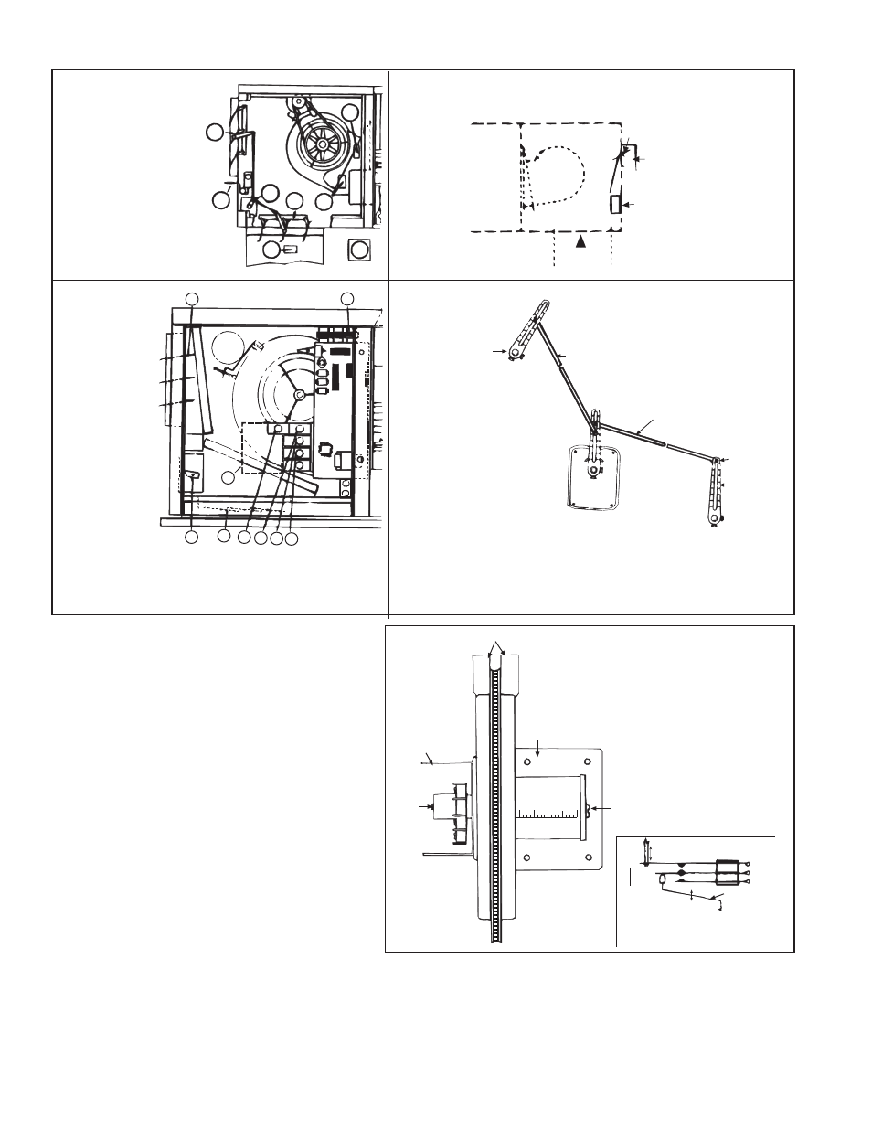
FIGURE 41A - Control
Locations for Air Inlet/
Damper Options on Indoor
Models XE/HXE
FIGURE 41B - Location of Controls for 30% Outside Air Hood
and Damper Options (AR6 or AR7) - Outdoor Models only
FIGURE 41D - Example of
Outside Air and Return
Air Damper Linkage
Damper Linkage - When
units are equipped with
dampers, the dampers are
closed during shipment. When
there are both return air and
outside air dampers, the
return damper linkage
must be adjusted prior to
use.
7
8
1
2
3 4 5 6
9
FIGURE 41C -
Control
Locations for
100% Outside
Air and 100%
Return Air
Damper
Options on
Outdoor
Models
1 Damper Motor
2 Return Air
Damper
3 Potentiometer
4 Potentiometer
5 Mixed Air
Controller
6 Warmup Control
34. Optional Dampers and Controls (cont'd)
1 Outside Air Damper
2 Return Air Damper
3 Damper Motor
4 Potentiometer
5 Mixed Air Controller
6 Outside Air
Changeover
7 Warmup Control
8 Potentiometer
1. Loosen the set screw on the return air damper rod at the damper arm.
2. Manually open the return air dampers. While the dampers are opening, the
damper rod and arm will automatically move to their correct positions.
3. Tighten the set screw.
7 Outside Air Damper
8 Damper Motor Transformer
9 DDC Interface Control
Electric Box
Span
Adjust
Screw
Mounting Plate
Pressure Taps
Low
High
Pressure
Adjust Screw
Increasing
Decreasing
Linkage to
Diaphragm
Low
Common
High
Span Adjustment
Span of
floating
contact
Switching action in the pressure null switch
FIGURE 41D -
Pressure Null
Switch (used with
Inlet Air Option
AR23)
3. Connect the pressure taps on the top of the switch to sources of air pressure
differential. Metal tubing with 1/4" O.D. is recommended, but any tubing
system which will not unduly restrict the air flow may be used. To maintain a
positive building pressure, vent the low pressure tap to the outdoors and allow
the high pressure tap to monitor building pressure. To maintain a negative
building pressure, reverse the functions of the high and low pressure taps. In
either case, be sure that the outdoor vent is protected from the wind and
screened from insects.