Roof curb assembly and installation – Reznor XE Unit Installation Manual User Manual
Page 10
Form I-XE/CRGB/RPB, P/N 131782 Rev 5, Page 9
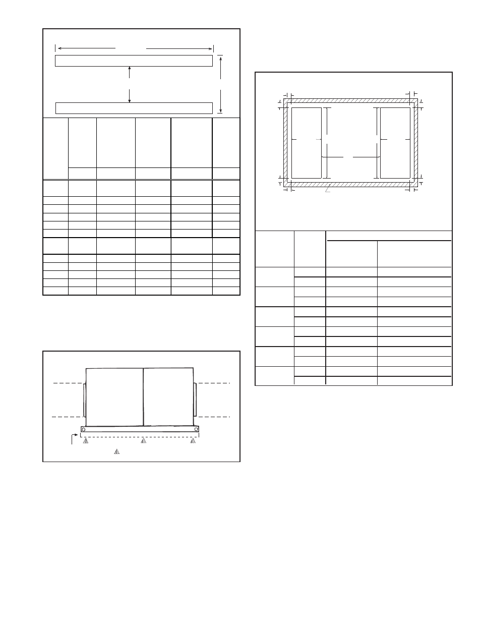
FIGURE 6A - Mounting Support Dimensions (inches/mm)
A
B
4x4 Treated Lumber
Leave both
ends open
for ventilation.
Blower
Cabinet
Furnace
Section
Field
Supplied
Duct
4x4 Treated
Lumber
= Cross Support Locations
Field
Supplied
Duct
FIGURE 6B - Cross-Support Locations
The field-supplied, weather-resistant cross-support structure must be
adequate for the weight of the system (including air conditioning coil if
applicable), and all cross-supports should run the entire width of the
system supporting the 4x4 wooden rails at the recommended locations.
If the treated wooden rails are not being placed directly on the roof
surface, cross-supports should be placed underneath the rails at the
ends of the unit and at all cabinet "joints" (between the blower cabinet
and the furnace section; between the furnace and the optional downturn
plenum or coil cabinet; and between a coil cabinet and a downturn
plenum). See FIGURE 6B.
Mounting on a Roof Curb - Whether using an optional roof curb
available with the system or a field-supplied curb, the curb must be
secure, square and level. The top surface of the roof curb must be
caulked with 1/4" x 1-1/4" sealant tape or two 1/4" beads of suitable
sealant. The unit must be sealed to the curb to prevent water leakage
into the curb area due to wind blown rain and capillary action. Except
for the curb assembly details which are specific to the optional roof
curb available with the system, the information and requirements in
this section apply to all curbs. See FIGURE 8, page 10, and the curb
installation instructions below.
FIGURE 7 - Duct Opening Dimensions in Relation to Roof
Curb Option - inches (mm)
1-5/8
(41)
1-5/8
(41)
1-5/8 (41)
1-5/8 (41)
1-5/8 (41)
1-5/8 (41)
19-1/2
(495)
19-1/2
(495)
H
H
G
Return
Duct
Supply
Duct
Roof Curb
1-5/8
(41)
1-5/8
(41)
•
1-5/8" (41mm) is the measurement from duct opening to
inside edge of roof curb.
•
Duct openings should be 1" larger than the duct size for
installation clearance.
Roof Curb Assembly and Installation Instructions (Refer to
FIGURE 8, page 10)
Curbs are shipped unassembled. Field assembly and mounting on the
roof are the responsibility of the installer. All required hardware neces-
sary to complete the assembly is supplied.
Before installing roof curb, verify that the size is correct for the
system being installed.
1. Position curb cross rails and curb side rails as illustrated in
FIGURE 8, page 10. If there are two side pieces to a side, fasten
them with splice plates and hardware as illustrated in the splicing
detail drawing. Join the corners as illustrated in the corner detail.
2. Check the assembly for squareness. Adjust the roof curb so that
the diagonal measurements are equal within a tolerance of + or -
1/8" (3mm).
3. Level the roof curb. To ensure a good weather tight seal between
the curb cap and the roof curb, the roof curb must be leveled in
both directions with no twist end to end. Shim level as required
and secure curb to roof deck before proceeding with flashing.
4. Install field-supplied flashing.
5. Before placing the unit into position, apply furnished 1/4" x
1-1/4" foam sealant tape to top surface of curb, making good butt
joint at corners. The unit must be sealed to the curb to prevent
water leakage into the curb area due to blown rain and capillary
action.
Model
G
Series
H
With Downturn
w/Cooling Coil Cabinet
CRGB and
Plenum, Option
w/Downturn, Options
RPB Sizes
AQ5 or AQ8
AU 11, 12, 13, or 14
75, 100,
17-3/8"
38-5/8"
75-31/32"
125
441mm
981mm
1930mm
150, 175
22-7/8
38-5/8
81-15/32
581mm
981mm
2069mm
200, 225
28-3/8
38-5/8
86-31/32
721mm
981mm
2209mm
250, 300
36-5/8
38-5/8
95-1/4
930mm
981mm
2419mm
350
42-1/8
38-5/8
100-3/4
1070mm
981mm
2559mm
400
47-5/8
38-5/8
106-1/4
1210mm
981mm
2699mm
Bottom Duct Connections - The blower section and optional down-
turn plenum have duct flanges for connection to return air and supply
air ducts. Duct opening sizes and curb spacing shown in FIGURE 7 is
for currently manufactured curbs that are available from the system
manufacturer.
Standard
He ate r
and
Blowe r
Package
Wi th Factory-
Instal l e d
Downturn
Pl e num
Cabi ne t
(O ption AQ )
W i th
Shippe d-
Se parate
C ool ing
C oil
C abi ne t
(O pti on AU)
Wi th Shi ppe d-
Se parate
C ool i ng C oi l
C abi ne t wi th
Downturn
Ple num
(O pti on AU)
A
ll
Co
nfi
g
ur
a
ti
o
ns
"A"
"A"
"A"
"A"
"B"
75, 100,
125
60-5/8"
84-9/16"
98-3/8"
122-1/4"
24-5/16"
150, 175
60-5/8"
84-9/16"
103-7/8"
127-7/8"
29-13/16"
200, 225
60-5/8"
84-9/16"
109-3/8"
133-3/8"
35-5/16"
250, 300
60-5/8"
84-9/16"
117-5/8"
141-5/8"
43-9/16"
350
60-5/8"
84-9/16"
123-1/8"
147-1/8"
49-1/16"
400
60-5/8"
84-9/16"
128-5/8"
152-5/8"
54-1/2"
75, 100,
125
1540mm
2148mm
2499mm
3105mm
618mm
150, 175
1540mm
2148mm
2638mm
3248mm
757mm
200, 225
1540mm
2148mm
2778mm
3388mm
897mm
250, 300
1540mm
2148mm
2988mm
3597mm
1106mm
350
1540mm
2148mm
3127mm
3737mm
1246mm
400
1540mm
2148mm
3267mm
3877mm
1384mm
M
o
del Series
CRGB
a
nd RP
B Sizes