Direct digital control system, Pilot and ignition systems, Optional electronic modulation (cont'd) – Reznor XE Unit Installation Manual User Manual
Page 29: Or bacnet
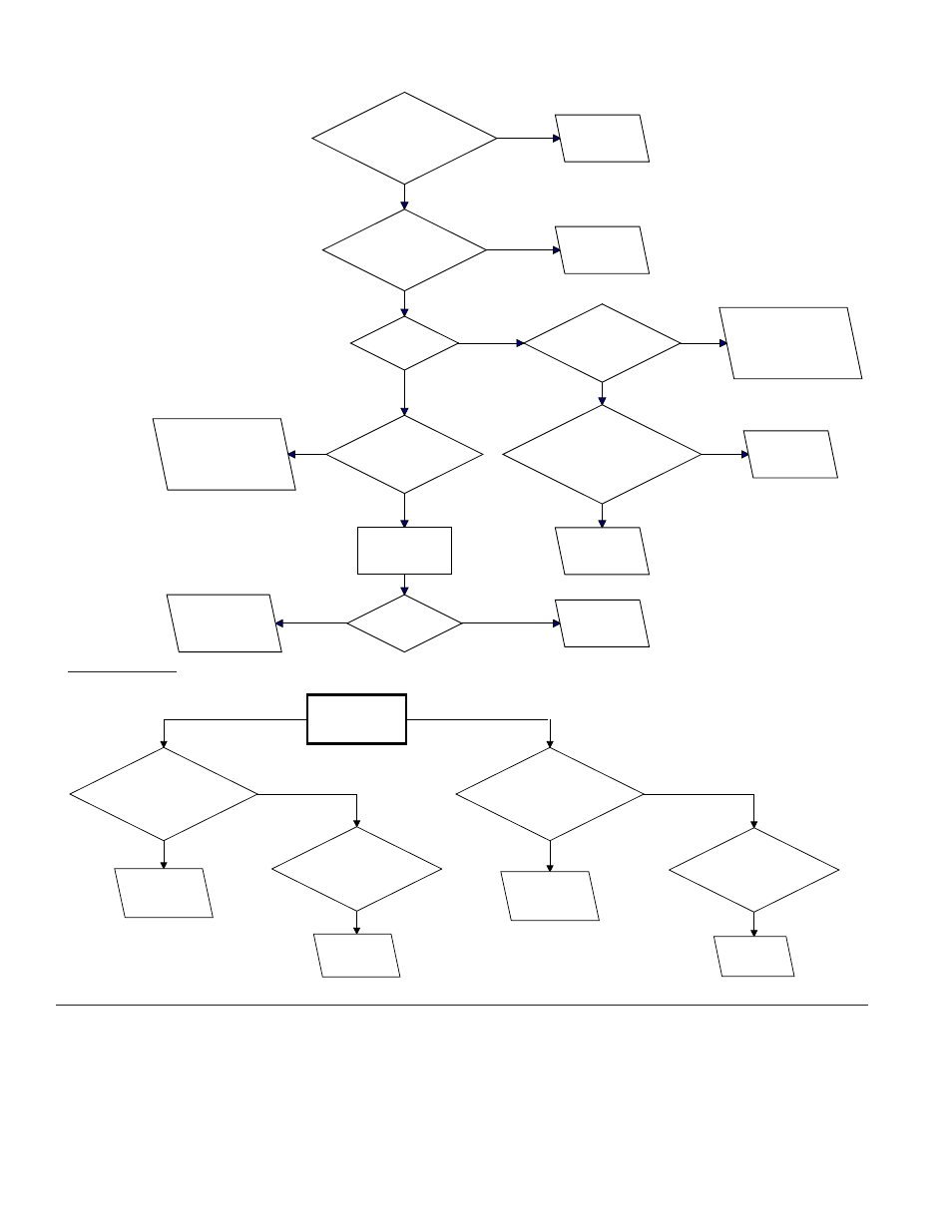
Form I-XE/CRGB/RPB, Page 28
Measure manifold
pressure
during burner cycling.
When the
manifold pressure is
BELOW 1.0" w.c., is there a steady
voltage between Terminal 95
and Terminal 7?
Replace secondary
manifold pressure
switch.
While the
burner is cycling, is
there a steady voltage
between Terminal 84 and
Terminal 2?
Replace the
primary manifold
pressure switch.
When the
manifold pressure is
ABOVE 1.5" w.c., is there a steady
voltage between Terminal 95
and Terminal 7?
Replace secondary
manifold pressure
switch.
Is there voltage
between Terminal 4 of the
ignition premissive relay and
Terminal 7?
Replace ignition
permissive
relay.
YES
NO
YES
NO
YES
NO
Is there 24 volts
between Terminal 2 on #1
Time Delay Relay and
Terminal 7?
Go to
Troubleshooting
Chart for heater.
Is there 24 volts
between Terminal 84 and
Terminal 7?
Is the
damper open?
Is there voltage
between Terminal 88 and
Terminal 7?
Is there voltage
between Terminal 4 on
ignition permissive relay and
Terminal 7?
Replace #1 time
delay relay.
Replace ignition
permissive
relay.
Check combustion
damper lower end switch
adjustment. If necessary,
replace end switch.
Is there voltage
between Terminal 87 and
Terminal 7?
Check combustion
damper lower end switch
adjustment. Replace end
switch if necessary.
Place a jumper
across Terminal
86 and Terminal 7.
Did the
damper close?
Replace motor
run time delay
relay.
Replace combustion
damper gear motor.
Replace primary
manifold
pressure switch.
YES
NO
YES
NO
YES
NO
YES
NO
YES
NO
NO
YES
YES
NO
26. Direct Digital Control System -
Model Series CRGB and RPB
The heater is equipped with a specially programmed Johnson Controls
Metasys
®
direct digital control unit. The unit is mounted in the blower
cabinet; see FIGURE 26. If interfacing with the building's Johnson Con-
trols Building Automaton System, follow the instructions included in
the owner's envelope. The control unit has two analog outputs, six
analog inputs, six binary outputs, and four binary inputs.
25C. and 25D. Electronic
Modulation between 20% -
28% and 100% Firing Rate
(cont'd)
25. Optional Electronic Modulation (cont'd)
Troubleshooting Guide for
Checking Bypass
Combustion Air Damper
Safety Circuit on Model
RPB with Option AG39 or
AG40
General Instructions: For each step,
check to ensure that the wiring is not
defective and that the wiring connec-
tions are secure.
Symptom: Main burners are inopera-
tive. Assumes that 24 volts is available
between Terminal 2 and Terminal 7.
Symptom - Part 2:
Steady call for heat - burner cycles. Assumes that 24 volts is available between Terminals 11 and 7 and Terminals 2 and 7.
(NOTE: With the addition of a field-supplied integrator, the controller
can also be used with a Honeywell or Siebe building management sys-
tem or with any Lonworks
TM
or BacNet
TM
based protocol system.)
The unit can also operate the system as a stand alone control at the
default settings.
Depending on which option was ordered, the following functions are
available for monitoring and control through the building's environmen-
tal system. Option D1 has modulating dampers and modulating gas