Reznor XE Unit Installation Manual User Manual
Page 34
Form I-XE/CRGB/RPB, P/N 131782 Rev 5, Page 33
CAUTION: Water reservoir must be drained
and pump motor turned off when outside
temperature falls below 32°F(0°C). Pump must
never be operated without water in the
reservoir. See Hazard Levels, page 2.
Supply and Drain Water Connections
Float Valve (FIGURE 33) - In a module with pump and float
controls, a float valve maintains the appropriate water level in the
reservoir.
Use a field-supplied 1/4" diameter tubing with a compression nut
and tubing ferrule to connect the fresh water supply to the inlet of
the float valve. See FIGURE 33. Place nut and ferrule over tubing
and insert tubing into the float valve stem. Tighten nut securely.
Simulates
Side Panel
Use 1/4"
Tubing for
Fresh Water
Supply
Compression Nut
and Tubing Ferrule
(Inside
Cabinet)
Float
Valve
Rod
FIGURE 33 -
Connect Fresh
Water Supply to
Inlet of Float
Valve
An optional automatic fill and drain kit (Option CT) is available
that will automatically release supply water to the cooling mod-
ule when a call for cooling is made and drain all water from the
reservoir when the cooling switch is deactivated or a cooling ther-
mostat is satisfied. See FIGURE 34. If installing an optional fill
and drain kit, follow the instructions with FIGURE 34 (right).
Consult wiring diagram for electrical connections.
AquaSaver
TM
Timed Metering Control System - If the cooling
module is equipped with an optional timed metering system, con-
nect a 1/2" water line to the fitting on the side of the cooling
module. Due to various water pressures and installation condi-
tions, the water supply line may bang abruptly when the solenoid
valve in the AquaSaver
TM
system closes. This banging can be
minimized by installing an optional water hammer arrestor in the
supply line. When installing an optional water hammer arrestor,
select an indoor (above 32°F) location, either horizontal or verti-
cal, in line with and as close to the solenoid valve as possible.
Follow the manufacturer's instructions to install and maintain the
water hammer arrestor.
A freeze protection kit (Option CT5) is also available.
All Cooling Modules - A manual water shutoff valve should be
installed upstream of the cooling module inlet, at a convenient
non-freezing location, to allow the water supply to be turned on
and off. If necessary, install a bleed line between the manual valve
and the cooling module to allow drainage of the line between the
shutoff valve and the cooling module.
All cooling modules are equipped with an overflow and drain
fitting. The fittings are in the cabinet bottom and come complete
metering water system, it will not have these controls but will
have a solenoid valve with a timer assembly for controlling water
flow.
Installation Instructions - Evaporative
Cooling Module
The evaporative cooling module is factory assembled, installed
and wired. No additional roof mounting is necessary. Follow these
instructions to field connect the water supply and make neces-
sary checks and adjustments before operating the cooling module.
with a lock nut and a sealing gasket. Check these fittings for tightness before
installing the overflow and drain piping. The drain and overflow fitting will
accommodate a 3/4" garden hose thread and is tapped with a 1/2" female pipe
thread for iron pipe.
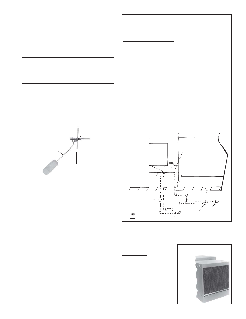
Instructions for Installing Optional Fill & Drain Kit
NOTE: Follow instructions included in the valve packages for attaching
valves to the water line only. The remainder of the installation instruc-
tions with the valves does not apply to this type of application.
Water Line Connections (See illustration below):
Supply (3-Way Valve) Connections - Connect the water supply line to "B"
(normally closed). Connect the water drain line to "A" (normally open).
Connect the middle outlet to supply the water to the cooling module reser-
voir.
Drain (2-Way Valve) Connections - Connect the drain pipe from the reser-
voir to the valve inlet. Connect the outlet side into the drain lines from the
cooling reservoir and the supply valve.
Electrical Connections (requires black and white 14-gauge wire) -
Refer to Wiring Diagram provided with the furnace:
WARNING: Risk of electrical shock. Disconnect the power.
1. Refer to the wiring diagram for terminal connections. (NOTE: If kit is
not ordered with the system, connections will not be shown on the
diagram. Terminal connections are specific to each system. Contact
the factory for terminal connections. Be prepared to provide all model
information.)
2. Run field-supplied black wire from the electrical compartment (terminal
on the wiring diagram) of the evaporative cooling module and connect to
the black wire on both the 3-way and the 2-way valve.
3. Run field-supplied white wire from the electrical compartment (termi-
nal on the wiring diagram) of the evaporative cooling module and con-
nect to the white wire on both the 3-way and the 2-way valve.
Evaporative
Cooling
Module
Float valve inlet water connection
(1/4 compression) or inlet water
connection to solenoid valve
for metering system (1/2 male fitting)
Overflow fitting -
3/4 garden
hose thread tapped
with 1/2 female NPT
Drain fitting - 3/4
garden hose thread
tapped with
1/2 female NPT
2-way solenoid valve
(normally open)
3-way
solenoid
valve
To drain
Pressure regulator
(10 psi max)
Service valve
Roof Line
= Field supplied
= Field-installed water piping
A (N.O.)
B (N.C.)
Water
inlet
FIGURE 34 - Water Connections including Optional Drain and
Fill Kit (pump and float controls)
Bleed Line Connection (Does not
apply to module with optional timed
metering system.) - Shipped in the
evaporative cooling module bottom
pan, find a 1/4" I.D. x 1/2" N.P.T.
nylon bleed line fitting (hose barb).
Thread the fitting into the female
adapter located opposite the pump/
inlet side of the water distribution
line. The hose barb will protrude
from the side of the cabinet (See FIG-
URE 35). Attach a 1/4" I.D. hose to
the barb and run the hose to the near-
est drain.
Install the
hose barb
and attach
bleed line.
FIGURE 35 - Bleed Line Con-
nection