Dimensions (cont'd) – Reznor XE Unit Installation Manual User Manual
Page 7
Form I-XE/CRGB/RPB, Page 6
D
7/8 (22)
7/8 (22)
2 (51)
Side View
DX Coil
Cabinet
Drain Pan
Outlet
(1 FPVC)
Suction Line
Connection
(1-5/8 or 2-1/8)
14-1/2
(368)
6-5/8
(168)
G
F
(Inside of Curb Cap)
E
(Curb Cap Length)
Liquid Line
Connection Knockouts
(alternate locations)
2-3/8
(60)
3-1/2(89)
3-1/4(83)
Bottom View
DX Coil
Cabinet
Coil
Header
Housing
Dimensions (inches ± 1/8; mm± 3)
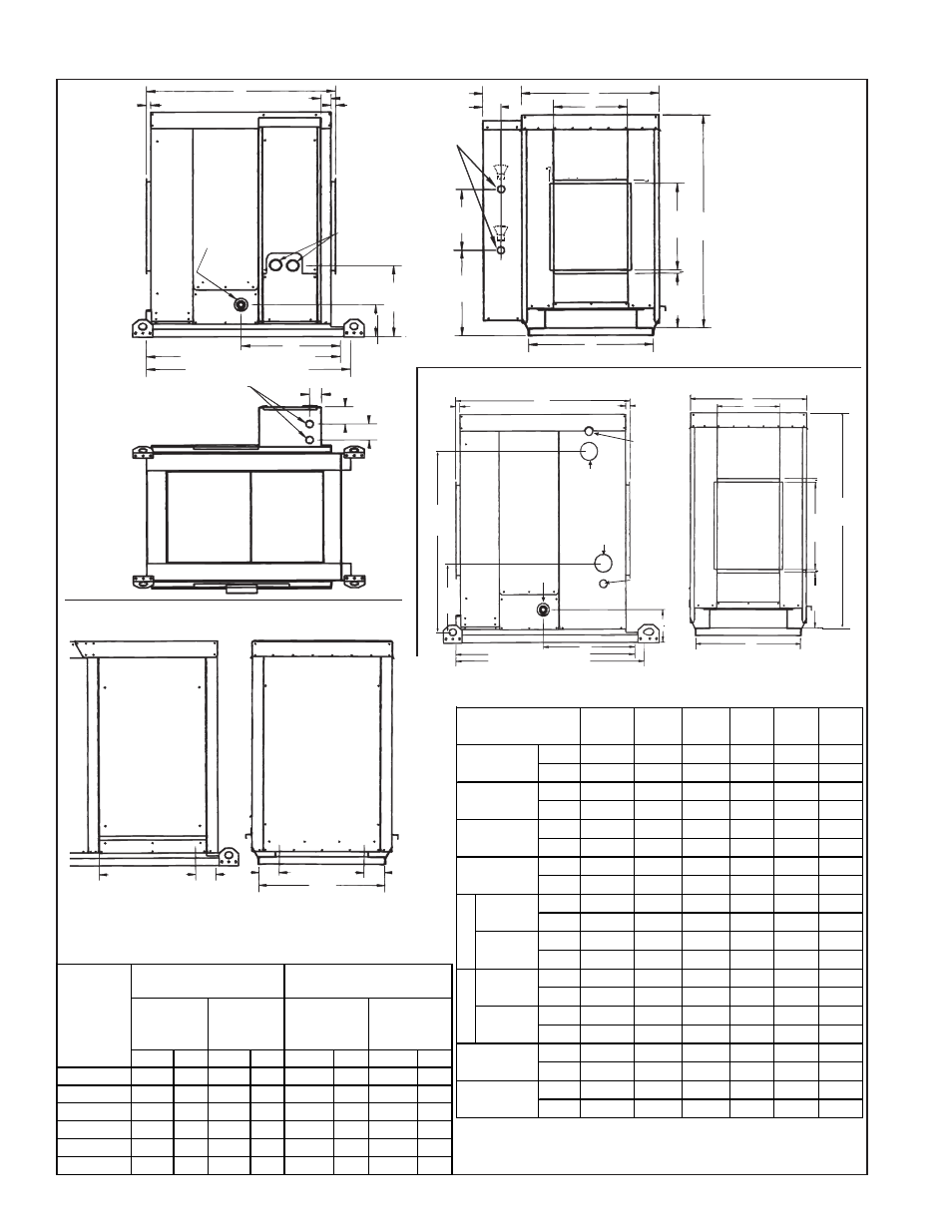
4. Dimensions (cont'd)
NOTE: For the length of a system with a cooling coil cabinet, see the
table on the left. Cooling coil cabinet is shipped separately and attached
in the field. See page 10 for roof curb dimensions.
Furnace S ize
75, 100,
125
150,
175
200,
225
250,
300
350
400
inches
28-1/2
34
39-1/2 47-3/4 53-1/4 58-3/4
mm
724
864
1003
1213
1353
1492
inches
15-1/4
20-3/4 26-1/4 34-1/2
40
45-1/2
mm
387
52
667
876
1016
1156
inches
25-7/8
31-3/8 36-7/8 45-1/8 50-5/8 56-1/8
mm
657
797
937
1146
1286
1426
inches
37-1/8
42-5/8 48-1/8 56-3/8
62
67-3/8
mm
943
1083
1222
1432
1575
1711
inches
40
45-5/8
51
59-3/8 64-7/8 70-3/8
mm
1016
1159
1295
1508
1648
1788
inches
64
69-5/8
75
83-3/8 88-7/8 94-3/8
mm
1626
1768
1905
2118
2257
2397
inches
38-1/8
43-5/8 49-1/8 57-3/8
63
68-3/8
mm
968
1108
1248
1457
1600
1737
inches
62-1/8
67-5/8 73-1/8 81-3/8
87
92-3/8
mm
1578
1718
1857
2067
2210
2346
inches
19-1/2
22-1/4
25
29-1/8 31-7/8 34-5/8
mm
495
565
635
740
810
879
inches
17-3/8 22-7/8 28-3/8 45-1/8 50-5/8 56-1/8
mm
441
581
721
1146
1286
1426
A
B
C
D
E
F
G
J
Without
Downturn
With
Downturn
Without
Downturn
With
Downturn
Chilled Water Cooling Coil Cabinet in Options AU2, AU11, AU12
Refrigerant
R22 (DX)
Coil
Cabinet -
Options
AU3, AU13,
AU14
Downturn Plenum Cabinet (factory attached to
either type of Cooling Coil Cabinet)
Front View
DX Coil
Cabinet with
Horizontal
Discharge
(Option AU3)
Liquid Line
Connections
(7/8 or 1-3/8)
5-1/8 (130)
8 (203)
3/4
(19)
3/4
(19)
A
B
3/4
(19)
18
(457)
44-1/4
(1124)
12-1/2
(318)
16-1/4
(413)
C
11-1/4
(286)
Side View
Chilled
Water Coil
Cabinet
F
(Inside of Curb Cap)
E
(Curb Cap Length)
D
7/8 (22)
Supply
Connection
2-1/2 NPT
G
7/8 (22)
Return
Connection
2-1/2 NPT
Coil Vent
1/2 NPT
Coil Drain
Connection
1/2 NPT
Drain Pan
Connection
1 FPVC)
6-5/8
(168)
38-3/8
(975)
15-1/4
(387)
Front View
CW Coil
Cabinet with
Horizontal
Discharge
(Option AU2)
44-1/4
(1124)
18
(457)
3/4
(19)
11-1/4
(286)
C
A
B
3/4
(19)
Side View
Optional
Downturn
Plenum
Cabinet
4-1/4
(108)
19-1/2 (495)
Discharge Air
J
(Discharge Air)
C
Front View
Optional
Downturn
Plenum
Cabinet
Side View
Optional
Downturn
Plenum
Cabinet
4-1/4
(108)
4-1/4
(108)
Discharge Damper Note: Optional two-position discharge dampers
in Option AU12 or AU14 fit in the discharge air opening. The
damper motor fits inside the downturn cabinet. See field wiring
instructions in Paragraph 36.
FIGURE 1D -
Optional Cooling
Coil Cabinets with
DX or Chilled
Water Coil, with
or without
Downturn Plenum
Cabinet (Applies
to Outdoor
Models)
inches
mm
inches
mm
inches
mm
inches
mm
75, 100, 125 29-1/8 740 37-1/8 943
98-1/2 2502 121-5/8 3069
150, 175
34-5/8 879 42-5/8 1083
104
2642 127-1/2 3229
200, 225
40-1/8 1019 48-1/8 1222 109-1/2 2781 132-5/8 3369
250, 300
47-1/8 1197 55-1/8 1400 117-3/4 2991 140-7/8 3578
350
53-3/8 1356 61-3/8 1559 123-3/8 3134 146-1/2 3721
400
58-7/8 1495 66-7/8 1698 128-3/4 3270 151-7/8 3858
Model
S eries
CRGB and
RPB S ize
w/Cooling
Coil Cabinet
w/Downturn
w/Chilled
Water Coil
Cabinet
Width of Cabinets (not
curb )
Length of All S ystem
Cabinets (not curb )
w/DX Coil
Cabinet
w/Cooling
Coil Cabinet
only