Discharge dampers – Reznor XE Unit Installation Manual User Manual
Page 40
Form I-XE/CRGB/RPB, P/N 131782 Rev 5, Page 39
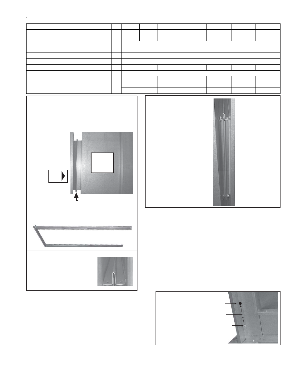
b) Position the assembled connectors so that the horizon-
tal screw holes will be in the top piece at the open side
(See FIGURE 46C). In this position, insert the
assembled top and bottom connectors (FIGURE 46B)
into the space between the furnace and cooling coil
cabinet.
Tap with a hammer first on the side, then on the top,
and last on the bottom of the assembled duct connector
until it is seated over the duct flanges.
FIGURE 46A -
1) Place the cooling coil cabinet on the curb;
2) remove the lifting lugs; and
3) slide the cabinet so that the duct flange on the
cooling coil cabinet butts
against the duct
flange on the
furnace.
Furnace
Discharge
with Duct
Flange
Duct Flanges
A i r -
flow
Cooling
Coil
Cabinet
FIGURE 46B - Assemble top, bottom, and one side
of the duct connector pieces using the 3/4"
sheetmetal screws
FIGURE 46C - The end of
the top connector on the
"open side" of the
connector assembly.
c) Position the remaining side connector. Use the driver ex-
tension to insert the screws that attach the side connector
to the top and bottom connectors. See FIGURE 46D.
FIGURE 46D - Position the
remaining side connector
over the duct flanges.
Attach to the top and
bottom connectors with 3/
4" screws creating a "U"
shaped rectangular frame
that joins the duct flanges
on all four sides.
Top
screws
should be
vertical.
5. Wiring Instructions - Apply to Downturn Plenum Cabinet with Op-
tional Discharge Dampers Only - If installing an Option AU12 or AU14
cooling coil cabinet with a downturn plenum cabinet equipped with op-
tional discharge dampers, the damper motor wires must be connected to the
terminal blocks in the furnace electrical compartment. If the coil cabinet
being installed does not include a downturn plenum with a discharge damper,
skip Step 5 and proceed to Step 6.
a) Drill three 7/8" holes as instructed below. Be sure all holes are free of burrs.
First Hole:
1) Remove the control side door on the discharge plenum.
2) Locate the discharge damper motor. Connected to the motor are three
wires in lengths adequate to reach the furnace section.
3) Refer to FIGURE 46E. On the leg of the downturn plenum next to the
cooling coil cabinet locate the mounting screw illustrated. Measure up
6" (152mm). At same centerline as the screw, drill the first 7/8" hole.
Factory-Supplied Parts for Attaching Cabinet to Furnace
Description
Qty 75, 100
125
150, 175
200, 225
250, 300
350
400
107426
107427
107428
107429
106338
106339
106340
14"
16-3/4"
21-1/4"
27-3/4"
36"
41-1/2"
47"
Side Duct Connectors Connectors
2
#14 x 3/4" long Sheetmetal Screws
8
Left Side Filler Panel
1
Right Side Filler Panel
1
Top Filler Panel
1
172360
172361
172362
172363
172364
Insulation, 1"x42"x9", for Side Filler Panels
2
#10 x 1/2" long Sheetmetal Screws
(_)
(21) 11813
(22) 11813
(24) 11813
(25) 11813
(26) 11813
Rubber Gasket Strip
103606
103607
103608
103609
103610
3/32" x 1-1/8" x
40-1/8"
45-5/8"
53-7/8"
59-3/8"
64-7/8"
Top/Bottom Duct Connectors
172546
172359
106305
34-5/8"
( 19) 11813
2
1
106395, 19-1/2" (495mm) long
105171
172357
172358
FIGURE 46E
3) Drill 7/8" Hole
2) Measure up
6" (152mm)
1) Locate
Mounting Screw
Second Hole:
1) Remove the cooling coil access panel(s).
2) Locate the coil blockoff plate. Measure up 4" (102mm) from the
bottom of the blockoff plate. At that location, find the centerpoint of