Optional equipment, 100% outside air hood, Optional equipment 100% outside air hood – Reznor XE Unit Installation Manual User Manual
Page 32: Optional accessories, 100% outside air hood (outdoor models), Check installation after start-up
Form I-XE/CRGB/RPB, P/N 131782 Rev 5, Page 31
Check installation after start-up
With the unit in operation, measure manifold gas
pressure. High fire manifold pressure for natural gas
should be 3.5" w.c. and 10" w.c. for propane gas. See
Paragraph 11.
Turn the unit off and on, pausing two minutes between
each cycle. Observe for smooth ignition. On two-stage
or modulating burner systems, manipulate temperature
adjustment slowly up and down to see if control is
sequencing or modulating properly. Raising temperature
setting drives burner on or to full fire.
Observe burner flame at full fire. Natural gas flame
should be about 1-1/2" in height with blue coloring.
Propane gas flame should be approximately the same
length with blue coloring. Yellow tipping may appear on
propane gas. If yellow extends beyond 1/2 to 3/4",
adjust air shutters. See Paragraph 29.
Close all panels tightly. With the heater on, check limit
control by completely blocking off distribution air. The
limit control should open within a few minutes, shutting
off the gas supply to the main burners.
If the system is equipped with an optional dirty filter
switch, set the switch. Follow the instructions in
Paragraph 35C.
Place "Owner's Envelope" containing Limited Warranty
Card, this booklet, and any optional information in an
accessible location near the heater. Follow the instruc-
tions on the envelope.
DANGER: The gas burner in this gas-fired equipment
is designed and equipped to provide safe, complete
combustion. However, if the installation does not permit
the burner to receive the proper supply of combustion
air, complete combustion may not occur. The result is
incomplete combustion which produces carbon monoxide,
a poisonous gas that can cause death. Safe operation of
indirect-fired gas burning equipment requires a properly
operating vent system which vents all flue products to
the outside atmosphere. FAILURE TO PROVIDE
PROPER VENTING WILL RESULT IN A HEALTH
HAZARD WHICH COULD CAUSE SERIOUS
PERSONAL INJURY OR DEATH.
Always comply with the combustion air requirements in
the installation codes and instructions. Combustion air
at the burner should be regulated only by manufacturer-
provided equipment. NEVER RESTRICT OR
OTHERWISE ALTER THE SUPPLY OF
COMBUSTION AIR TO ANY HEATER. Indoor units
installed in a confined space must be supplied with air
for combustion as required by Code and in Paragraph
6A of this heater installation manual. MAINTAIN THE
VENT SYSTEM IN STRUCTURALLY SOUND AND
PROPERLY OPERATING CONDITION.
OPTIONAL ACCESSORIES
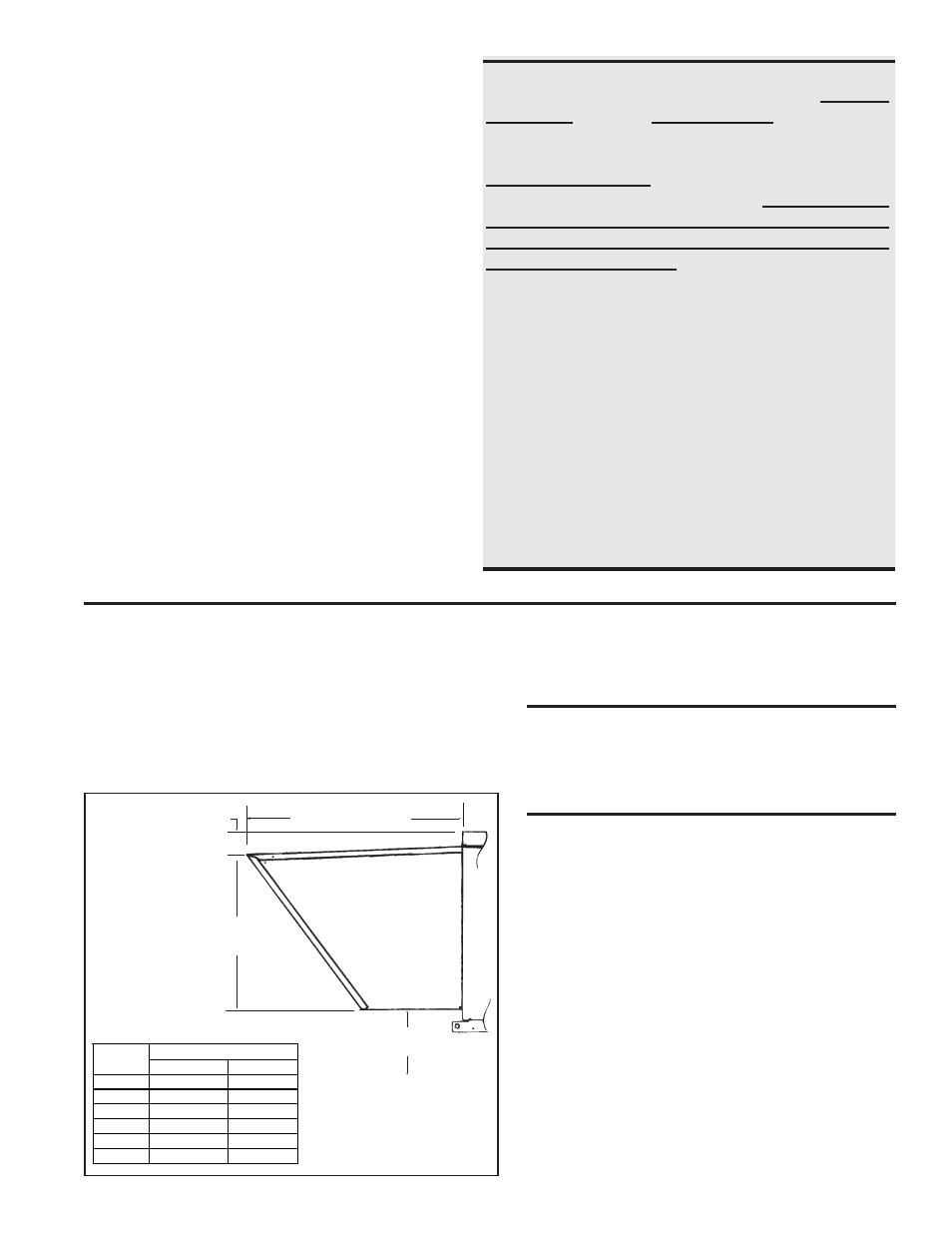
31. 100% Outside Air Hood (outdoor models)
Outside air hood (Option AS2) is a weatherized, screened hood designed to
be field assembled and installed around the horizontal inlet air opening of the
blower cabinet. The air hood includes factory-assembled louvers (U.S. Patent
4,999,037) designed to help eliminate moisture from the inlet air. Complete
installation instructions are packaged with the air hood option.
FIGURE 29 -
Dimensions
of Optional
Outside Air
Hood
Optional
100%
Outside
Air Hood
43-17/32 (1106mm)
4-5/8
(117mm)
31-11/32
(796mm)
14 (356mm)
minimum
NOTE: The width of
the outside air hood is
the same as the width
of the blower cabinet.
CAUTION: It is recommended that the inlet
to the outside air hood NOT be facing into the
prevailing wind. Allow 14" (356mm) minimum
clearance from the bottom of the air hood to
the mounting surface.
Installation Instructions - 100% Outside Air
Hood
Refer to FIGURE 30. All screw ends except those across the bot-
tom should be inside the air hood.
To avoid possible damage, it is recommended that the outside air
hood be installed after the system has been placed on the roof. The
air hood should be installed before the heater is operated. Do not
install the hood while the system (furnace or blower) is in opera-
tion.
1. Top Panel - On the air inlet side of the blower cabinet, remove
the factory-installed screws attaching the blower cabinet top.
Slide the air hood top panel underneath the edge of the blower
cabinet top. The edge of the air hood top panel must be
between the blower cabinet top and the end panel. Reinsert
all of the sheetmetal screws.
2. Side Panels - Slide the air hood right side panel into the groove
in the blower cabinet end panel. Be sure that the side panel is
underneath and to the inside of the air hood top panel. Attach to
the blower cabinet and the air hood top using the required num-
ber of sheetmetal screws. Repeat with the left side panel.
inches
mm
75,100,125
53-3/8
1356
150,175
34-1/8
867
200,225
39-5/8
1006
250,300
47-7/8
1216
350
53-3/8
1356
400
58-7/8
1495
Width of Outside Air Hood
Size